
Installation Guide
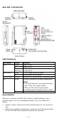
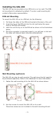
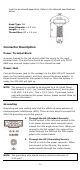
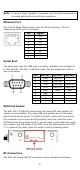
Table Of Contents

- 6 -
NOTE
If using a Class I adapter, the power cord must be connected to
a socket-outlet with an earthing connection.
Ethernet Port
The 10/100 Mbps Ethernet port uses the RJ45 connector. The pin
assignment of the port is as below:
Pin
Signal
1
Tx+
2
Tx-
3
Rx+
4
–
5
–
6
Rx-
7
–
8
–
Serial Port
The serial port uses the DB9 male connector. Software can configure it
for the RS-232, RS-422, or RS-485 mode. The pin assignment of the
port is as below:
Pin
RS-232
RS-422
RS-485
1
DCD
TxD-(A)
–
2
RxD
TxD+(B)
–
3
TxD
RxD+(B)
Data+(B)
4
DTR
RxD-(A)
Data-(A)
5
GND
GND
GND
6
DSR
–
–
7
RTS
–
–
8
CTS
–
–
9
–
–
–
SIM Card Socket
The AIG-100-T-AP/EU/US comes with two nano-SIM card sockets for
cellular communication. The nano-SIM card sockets are on the same
side as the antenna panel. To install the cards, remove the screw and
the protection cover to access the sockets, and then insert the nano-
SIM cards into the sockets directly. You will hear a click when the cards
are in place. The left socket is for SIM 1 and the right socket is for SIM
2. To remove the cards, push the cards in before releasing them.
RF Connectors
The AIG-100 comes with RF connectors to the following interfaces.