AIG-100 Series Quick Installation Guide Version 1.0, October 2022 Technical Support Contact Information www.moxa.com/support 2022 Moxa Inc. All rights reserved.
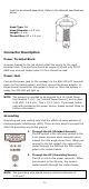
Overview Moxa AIG-100 Series can be used as smart edge gateways for data preprocessing and transmission. The AIG-100 Series focuses on IIoTrelated energy applications and supports various LTE bands and protocols.
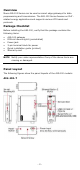
AIG-101-T-AP/EU/US LED Indicators LED Name SYS LAN1/LAN2 COM1/COM2 LTE Status Green Off Green (blinking) Green Off Orange Green Function Power is ON Power is OFF The gateway will reset to the default configuration 10/100 Mbps Ethernet mode Ethernet port is not active Serial port is transmitting or receiving data Cellular connection has been established Off NOTE: Three levels based on the signal strength 1 LED is ON: Poor signal quality 2 LEDs are ON: Good signal quality All 3 LEDs are ON: Excellent si
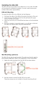
Installing the AIG-100 The AIG-100 can be mounted on to a DIN rail or on to a wall. The DINrail mounting kit is attached by default. To order a wall-mounting kit, contact a Moxa sales representative. DIN-rail Mounting To mount the AIG-100 on to a DIN rail, do the following: 1. 2. 3. 4. Pull down the slider of the DIN-rail bracket at the back of the unit Insert the top of the DIN rail into the slot just below the upper hook of the DIN-rail bracket.
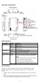
must be purchased separately. Refer to the detailed specifications below: Head Type: flat Head Diameter >5.2 mm Length >6 mm Thread Size: M3 x 0.5 mm Connector Description Power Terminal Block A person trained for the job should install the wiring for the input terminal block. The wire type should be copper (Cu) and only 28-18 AWG wire size and torque value 0.5 N-m should be used.
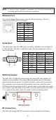
NOTE If using a Class I adapter, the power cord must be connected to a socket-outlet with an earthing connection. Ethernet Port The 10/100 Mbps Ethernet port uses the RJ45 connector. The pin assignment of the port is as below: Pin 1 2 3 4 5 6 7 8 Signal Tx+ TxRx+ – – Rx– – Serial Port The serial port uses the DB9 male connector. Software can configure it for the RS-232, RS-422, or RS-485 mode.
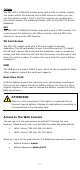
Cellular The AIG-100-T-AP/EU/US models come with a built-in cellular module. You must connect the antenna to the SMA connector before you can use the cellular function. The C1 and C2 connectors are interfaces to the cellular module. For additional details, refer to the AIG-100 Series datasheet. GPS The AIG-100-T-AP/EU/US models come with a built-in GPS module. You must connect the antenna to the SMA connector with the GPS mark before you can use the GPS function.