Manual Moxa Industrial Video Encoder VPort 351 Series Quick Installation Guide Fifth Edition, June 2008 © 2008 Moxa Inc., all rights reserved. Reproduction without permission is prohibited. Amplicon.co.uk IT and Instrumentation for industry Sales: +44 (0) 1273 570 220 Website: www.amplicon.co.uk Email: sales@amplicon.co.
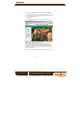
Manual Overview The VPort 351 is a high performance, 1-channel industrial video encoder that provides up to full D1 (720 x 480) @ 30 FPS video performance. The VPort 351 is designed to support multi-codecs, including MJPEG and MPEG4 algorithms. In addition, a continuous video pre/post event-trigger video record function is supported to enhance video surveillance systems.
Manual y y Built-in web server and RS-232 console for remote access & configuration y y y y y y TCP, UDP, and HTTP network transmission modes y DDNS (Dynamic DNS), UPnP and IP filtering supported 1 auto-sensing 10/100BaseT(X) Ethernet port or 100baseFX (SC connector) Allows simultaneous access of up to 10 clients Set video quality to CBR (constant bit rate) or VBR (variable bit rate) Full D1, 4CIF, VGA, QVGA, and CIF video resolution supported Timestamp and text overlay supported RS-232/RS-422/RS-485
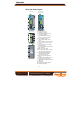
Manual VPort 351 Panel Layout VPort 351 Front Panel View VPort 351-M-SC Front Panel View 8 7 9 10 11 12 1 1 2 16 2 13 14 17 15 18 Top Panel View 1 4 RS-232 CONSOLE V1, V2: 12-32 VDC 12-30 VAC 2 5. 6 5 3 Rear Panel View 1. 2. 3. 4. 6. 7. 8. 9. 10. 19 11. 12. 13. 20 14. 19 15. 16. 17. 18. 19. 20.
Manual First-Time Installation and Configuration Before installing the VPort 351 video encoder, check to make sure that all items in the Package Checklist are in the box. In addition, you will need to use a notebook or PC equipped with an Ethernet port. Step 1: Select the Power Source The VPort 351 can be powered by a DC power input from 12 to 32 VDC, or an AC power input from 18 to 30 VAC. Two power inputs are provided for redundancy.
Manual NOTE The PTZ control protocol is not standardized. To use a particular PTZ control protocol, the video server must support the driver for that protocol. Currently, the VPort 351 supports PTZ control protocol drivers for: 1. Pelco D 2. Pelco P 3. DynaColor DynaDome If you need to use a protocol that is not on the list, you will need to contact the manufacturer of the camera to get the PTZ control commands, and then program its PTZ control in the VPort 351’s Custom Camera function.
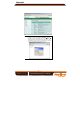
Manual NOTE You may download the VPort and Ether Device Configurator software from Moxa’s website at www.moxa.com. -7- 2. The Broadcast Search window will show a list of all switches and VPorts located on the network. The progress of the search will also be indicated. 3. When the search has ended, the Model Name, MAC address, and IP address of the EDS switches and VPorts will be listed in the Utility window.
Manual Network Environment without DHCP Server If your VPort 351 is connected to a network that does not have a DHCP server, then you will need to configure the IP address manually. The default IP address of the VPort 351 is 192.168.127.100 and the default subnet mask is 255.255.255.0. Note that you may need to change your computer’s IP address and subnet mask so that the computer is on the same subnet as the VPort.
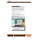
Manual Step 8: Accessing the Homepage of the VPort 351’s web-based manager After installing the ActiveX Control component, the homepage of the VPort 351’s web-based manager will appear. Check the following items to make sure the system was installed properly: 1. 2. 3.
Manual NOTE After accessing the VPort 351’s web-based manager, administrators should access System Configuration Æ System Æ Account to set up the administrator’s password and enable the authentication function. The administrator account name is admin. An authentication window will pop up requesting the account name and password each time the VPort 351 is accessed. - 10 Amplicon.co.uk IT and Instrumentation for industry Sales: +44 (0) 1273 570 220 Website: www.amplicon.co.uk Email: sales@amplicon.co.
Manual Mounting Dimensions (unit=mm) 30.00 40.00 13.10 9.00 15.10 25.40 135.00 135.00 35.00 DlN-Rail DlN-Rail Kit Front View 105.00 Side View 3.5 6 57.05 66.80 25.29 6 39.54 10 10 5 18 13 46.61 27.20 48.30 13 7.75 30.50 7.75 23.56 DlN-Rail Kit 13.9 Rear View 18.2 13.9 Wall Mounting Kit DIN-Rail Mounting The aluminum DIN-Rail attachment plate should already be attached to the back panel of the VPort 351 when you take it out of the box.
Manual Wall Mounting (Optional) Follow the steps below to mount the VPort 351 on a wall or panel. STEP 1: Remove the aluminum DIN-Rail attachment plate from VPort 351, and then attach the wall mount plates, as shown in the diagrams below. Top plate ⇒ Bottom plate STEP 2: Mounting the VPort 351 on the wall requires 4 screws. Use the VPort 351, with wall mount plates attached, as a guide to 6.0 mm mark the correct locations of the 4 screws. The heads of the screws should be less than 6.
Manual ATTENTION Safety First! Be sure to disconnect the power cord before installing and/or wiring your Moxa switch. This device has UL508 approval. Use copper conductors only, 60/75°C, Tighten To 4.5 pound-inches. For use in Pollution Degree 2 Environment. ATTENTION Safety First! Calculate the maximum possible current in each power wire and common wire. Observe all electrical codes dictating the maximum current allowable for each wire size.
Manual Wiring the Redundant Power Inputs The VPort 351 has two power inputs, labeled PWR1 and PWR2, on the 6-pin and 8-pin terminal block connectors. Top and front views of the terminal block connectors are shown in the following figures. ATTENTION The power for this product is intended to be supplied by a Listed Power Unit, with output marked LPS, and rated to deliver 12 to 32 VDC at a maximum of 740mA, or 18 to 30 VAC at a maximum of 890mA.
Manual Wiring the Digital Inputs The VPort 351 has two digital inputs, labeled DI1 and DI2. Each DI consists of two contacts of the 6-pin terminal block connector located on the VPort’s top panel. Top and front views of one of the terminal block connectors are shown here. V1- V1+ V2- V2+ STEP 1: Insert the negative/positive DC or AC wires into the V-/V+ terminals.
Manual RJ45 (10-pin) to DB9(F) Cable Wiring RJ45 Plug Pin 1 1 DCD 2 DSR 3 RTS GND 4/7 5 TxD 6 RxD 8 CTS 9 DTR 1 6 7 5 3 2 8 4 DCD DTR CTS GND RxD TxD RTS DSR RJ45 (10-pin) to DB25 (F) Cable Wiring RJ45 Plug Pin 1 1 DCD 2 DSR 3 RTS GND 4/7 5 TxD 6 RxD 8 CTS 9 DTR 8 6 4 7 2 3 5 20 DCD DTR CTS GND RxD TxD RTS DSR 10/100BaseT(X) Ethernet Port Connection The 10/100BaseT(X) port located on the VPort 351’s front panel is used to connect to Ethernet-enabled devices.
Manual RJ45 (8-pin) to RJ45 (8-pin) Straight-Through Cable Wiring Straight-Through Cable Switch Port VPort Ethernet Port RJ45 Plug Pin 1 RJ45 Connector RJ45 Connector Cable Wiring 3 6 1 2 Tx+ TxRx+ Rx- 3 6 1 2 Rx+ RxTx+ Tx- RJ45 (8-pin) to RJ45 (8-pin) Cross-Over Cable Wiring Cross-Over Cable VPort Ethernet Port NIC Port RJ45 Plug Pin 1 RJ45 Connector (Rx+) (Rx-) (Tx+) (Tx-) RJ45 Connector Cable Wiring 3 6 1 2 Tx+ TxRx+ Rx- 1 2 3 6 Rx+ RxTx+ Tx- (Tx+) (Tx-) (Rx+) (Rx-) 100BaseFX Etherne
Manual LED Indicators Several LED indicators are located on the front panel of the VPort 351. The function of each LED is described in the table below.
Manual Hardware Reset A recessed RESET button is provided for restoring the system to the factory default settings. When the system fails to install properly, or operates abnormally, push the RESET button located on the top panel of the VPort 351 to restore the factory defaults. To restore the VPort 351 to the factory default settings, use a pointed object, such as a straightened paper clip or toothpick, to press the reset button continuously. When the STAT LED blinks in red, release the reset button.
Manual LED Indicators STAT PWR1 PWR2 FAULT VIDEO AUDIO TEST PTZ Power Input Consumption Mechanical Casing Dimension (W x D x H) Weight Installation Environmental Operating Temperature Storage Temperature Ambient Relative Humidity Regulatory Approvals Safety Hazardous Location EMI EMS Indicates if the system booted properly Power 1 Power 2 Can be configured to correspond to system alarm, power failure, video loss, or disconnected network Video input signal active Audio input signal in test mode PTZ contro
Manual Security y User level password protection y IP address filtering Recommended System Requirements y Pentium 4, 2.4 GHz or above y 512 MB memory or above y Windows XP/2000 with SP4 or above y Internet Explorer 6.x or above y DirectX 9.0c or above Software Bundled Free Moxa SoftDVR Lite 1- to 4-ch IP Surveillance Software for viewing & recording (please check the release information on Moxa’s website) - 21 - Amplicon.co.