
RISC-based Communication Platforms User's Manual UC-7420/7410


UC-7420/7410 User’s Manual Introduction
1-6
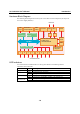
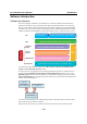
Hardware Block Diagram
The following block diagram shows the layout of UC-7420’s internal components (the layout for
UC-7410 is slightly different).
USB
Host
USB
controller
PCI to cardbus
Bridge
Moxa UART ASIC
PCI Bus
USB
Client
PCMCIA &
CompactFlash
Console LAN2 LAN1
RS-232/422/485
RS-232
Ethernet
Power
circuit
Power
Xscale IXP-422 266 MHz
32 MB Flash
128 MB SDRAM
LCM Display
& Keypad
7 85 61 2 3 4
PHY PHY
RTC
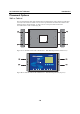
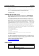
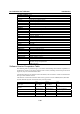
LED Indicators
UC-7420/7410 has 12 LED indicators on the top panel. Refer to the following table for
information about each LED.
LED Name Color Meaning
Ready Green Power is ON, and system is ready (after booting up)
Yellow 10 Mbps Ethernet connection
LAN1, LAN2
Green 100 Mbps Ethernet connection
Yellow Console port is receiving RX data from the serial device.
Console
Green Console port is transmitting TX data to the serial device.
Yellow Serial port is receiving RX data from the serial device. P1, P2, P3, P4,
P5, P6, P7, P8
Green Serial port is transmitting TX data to the serial device.