UC-7400 Hardware User’s Manual First Edition, March 2006 www.moxa.com/product Moxa Systems Co., Ltd. Tel: +886-2-8919-1711 Fax: +886-2-8919-1722 Web: www.moxa.com MOXA Technical Support support@moxa.com.tw Worldwide: The Americas support@moxa.
UC-7400 Hardware User’s Manual The Hardware described in this manual is furnished under a license agreement and may be used only in accordance with the terms of that agreement. Copyright Notice Copyright © 2006 Moxa Systems Co., Ltd. All rights reserved. Reproduction without permission is prohibited. Trademarks MOXA is a registered trademark of The Moxa Group. All other trademarks or registered marks in this manual belong to their respective manufacturers.
Table of Contents Chapter 1 Introduction ..................................................................................................1-1 Overview.................................................................................................................................. 1-2 Package Checklist....................................................................................................... 1-2 Product Features ...................................................................................
1 Chapter 1 Introduction Thank you for purchasing the MOXA UC-7400 RISC-based ready-to-run embedded computer. The product’s features include eight RS-232/422/485 serial ports, dual 10/100 Mbps Ethernet ports, 8 digital input channels and 8 digital output channels, a PCMCIA interface for wireless LAN communication, and CompactFlash and USB ports for mass storage disk expansion. All these make the UC-7400 series ideal for your embedded applications.
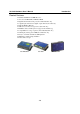
UC-7400 Hardware User’s Manual Introduction Overview The MOXA UC-7400 Series (herein after referred to as UC-7400) includes UC-7420, UC-7410, UC-7408, and UC-7402. These RISC-based ready-to-run embedded computers are ideal for embedded applications.
UC-7400 Hardware User’s Manual Introduction Product Features y y y y y y y y y y y y Intel XScale IXP-422 266 MHz Processor On-board 128 MB RAM, 32 MB Flash ROM Eight RS-232/422/485 serial ports (UC-7420/7410/7408 only) 8 digital input channels and 8 digital output channels (UC-7408 only) Dual 10/100 Mbps Ethernet USB 2.0 host for mass storage devices (UC-7420 only) PCMCIA, wireless LAN expansion (supports 802.11b/802.
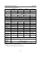
UC-7400 Hardware User’s Manual Introduction Product Hardware Specifications CPU RAM Flash LAN Serial Port Serial Protection Data Bits Stop Bits Parity Flow Control Speed Serial Console DI/DO USB 2.0 Hosts USB 1.
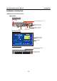
UC-7400 Hardware User’s Manual Introduction Hardware Introduction Appearance and Dimensions Appearance UC-7420 Rear View 12-48 VDC Power Input 10/100 Mbps Ethernet x 2 DC 12-48V PCMCIA LAN1 USB LAN2 Console USB 2.0 Host x 2, A Type Connector CF V+ V- CF x 1 RS-232 PPP/Console PCMCIA x 1 USB 1.
UC-7400 Hardware User’s Manual Introduction UC-7410 Rear View 12-48 VDC Power Input 10/100 Mbps Ethernet x 2 DC 12-48V LAN1 LAN2 Console V+ V- RS-232 PPP/Console USB 1.
UC-7400 Hardware User’s Manual Introduction UC-7408 Rear View 12-48 VDC Power Input 10/100 Mbps Ethernet x 2 DC 12-48V PCMCIA LAN1 LAN2 Console CF V+ V- CF x 1 USB 1.
UC-7400 Hardware User’s Manual Introduction UC-7402 Rear View 12-48 VDC Power Input DC 12-48V 10/100 Mbps Ethernet x 2 PCMCIA LAN1 LAN2 Console CF V+ V- CF x 1 PCMCIA x 1 USB 1.
UC-7400 Hardware User’s Manual Introduction Dimensions 44 mm [1.73"] 125 mm [4.92"] UC-7420/7410 197 mm [7.
UC-7400 Hardware User’s Manual Introduction 44 mm [1.73"] 125 mm [4.92"] UC-7408 197 mm [7.
UC-7400 Hardware User’s Manual Introduction 44 mm [1.73"] 125 mm [4.92"] UC-7402 197 mm [7.
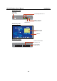
UC-7400 Hardware User’s Manual Introduction Hardware Block Diagram The following block diagram shows the layout of UC-7420 internal components. The following block diagram shows the layout of UC-7410 internal components.
UC-7400 Hardware User’s Manual Introduction The following block diagram shows the layout of UC-7408’s internal components. Ethernet USB Client Console LAN2 LAN1 RS-232 PCMCIA & CompactFlash PCI to cardbus Bridge PHY PHY Xscale IXP-422 266 MHz 32 MB Flash 128 MB SDRAM PCI Bus 2 3 Power circuit RTC Decoder Moxa UART ASIC 1 Power 4 5 6 7 8 D/I x 8 D/O x 8 RS-232/422/485 The following block diagram shows the layout of UC-7402’s internal components.
UC-7400 Hardware User’s Manual Introduction Reset Button Pressing the Reset button initiates a hardware reboot. The button plays the same role as a desktop PC’s reset button. In normal use, you should NOT use the Reset Button. You should only use this function if the software is not working properly. To reset an embedded linux system, always use the software reboot command />reboot to protect the integrity of data being transmitted or processed.
UC-7400 Hardware User’s Manual Introduction Figure A: UC-7420/7410 Universal Communicator—Wall Mounting Brackets (bottom view) Figure B: UC-7420/7410 Universal Communicator—Wall Mounting Brackets (top view) DIN-Rail Mounting The aluminum DIN-Rail attachment plate is included with the package. If you need to reattach the DIN-Rail attachment plate to UC-7400, make sure the stiff metal spring is situated towards the top, as shown by the following figures.
UC-7400 Hardware User’s Manual Introduction Hardware Connection Description This section describes how to connect UC-7420/7410 to serial devices for first time testing purposes. We cover Wiring Requirements, Connecting the Power, Grounding UC-7400, Connecting to the Network, Connecting to a Serial Device, Connecting to the Console Port, PCMCIA, CompactFlash, USB, and DI/DO. Wiring Requirements ATTENTION Safety First! Be sure to disconnect the power cord before installing and/or wiring your UC-7400.
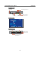
UC-7400 Hardware User’s Manual Introduction ATTENTION This product is intended to be mounted to a well-grounded mounting surface, such as a metal panel. SG: The Shielded Ground (sometimes called Protected Ground) contact is the left most contact of the 3-pin power terminal block connector when viewed from the angle shown here. Connect the SG wire to an appropriate grounded metal surface.
UC-7400 Hardware User’s Manual Introduction Connecting to the Console Port UC-7400’s console port is an 8-pin RJ45 RS-232 port. The port can be used to connect to the console utility from a remote console via a V90 or GPRS modem with PPP protocol. The pin definition is the same as for the serial ports (P1 to P8). For normal data acquisition applications, you should connect to UC-7400’s serial ports (P1 to P8) via a V90 or GPRS modem.
A Appendix A Service Information This appendix shows you how to contact MOXA for information about this and other products, and how to report problems.
UC-7420/7410 User’s Manual Service Information MOXA Internet Services Customer satisfaction is our number one concern, and to ensure that customers receive the full benefit of our products, Moxa Internet Services has been set up to provide technical support, driver updates, product information, and user’s manual updates. The following services are provided E-mail for technical support................................support@moxa.com.tw World Wide Web (WWW) Site for product information: ...................
UC-7420/7410 User’s Manual Service Information Problem Report Form MOXA UC-7400 Series Customer name: Company: Tel: Fax: Email: Date: 1. Moxa Product: UC-7420 2. Serial Number: UC-7410 UC-7408 UC-7402 _________________ Problem Description:Please describe the problem clearly. Include as many details as you can. This will help us reproduce the problem, and expedite the repair of your product.
UC-7420/7410 User’s Manual Service Information Product Return Procedure For product repair, exchange, or refund, the customer must: Provide evidence of original purchase. Obtain a Product Return Agreement (PRA) from the sales representative or dealer. Fill out the Problem Report Form (PRF). Include as much detail as possible for a shorter product repair time. Carefully pack the product in an anti-static package, and send it, pre-paid, to the dealer.