Moxa EtherDevice™ Switch EDS-408A/405A Series User’s Manual www.moxa.com/product Fourth Edition, June 2008 © 2008 Moxa Inc., all rights reserved. Reproduction without permission is prohibited.
Moxa EtherDevice™ Switch EDS-408A/405A Series User’s Manual The software described in this manual is furnished under a license agreement and may be used only in accordance with the terms of that agreement. Copyright Notice Copyright © 2008 Moxa Inc. All rights reserved. Reproduction without permission is prohibited. Trademarks MOXA is a registered trademark of Moxa Inc. All other trademarks or registered marks in this manual belong to their respective manufacturers.
Table of Contents Chapter 1 Introduction ...............................................................................................1-1 Inside the Future of Industrial Ethernet Technology ............................................................ 1-2 The trend in industrial communications and automation applications ...................... 1-2 Industrial vs. Commercial ......................................................................................... 1-2 Informative vs. Passive ................
Using Virtual LANs ................................................................................................ 3-41 Using Rate Limiting ........................................................................................................... 3-43 Configuring Rate Limiting ...................................................................................... 3-43 Using Auto Warning ...........................................................................................................
1 Chapter 1 Introduction Welcome to the Moxa EtherDevice Switch EDS-408A/405A Series, the world’s first intelligent Ethernet Device Switch designed especially for connecting Ethernet-enabled devices in industrial field applications.
EDS-408A/405A Series User’s Manual Introduction Inside the Future of Industrial Ethernet Technology The trend in industrial communications and automation applications As the world’s network and information technology becomes more mature, the trend is to use Ethernet as the major communications interface in many industrial communications, and automation applications.
EDS-408A/405A Series User’s Manual Introduction Optional Accessories y DR-4524—45W/2A DIN-Rail 24 VDC Power Supply with 85 to 264 VAC input y DR-75-24—75W/3.
2 Chapter 2 Getting Started This chapter explains how to access your Moxa EtherDevice Switch for the first time. There are three ways to access the switch: serial console, Telnet console, and web browser. The serial console connection method, which requires using a short serial cable to connect the switch to a PC’s COM port, can be used if you do not know the switch’s IP address.
EDS-408A/405A Series User’s Manual Getting Started RS-232 Console Configuration (115200, None, 8, 1, VT100) NOTE Connection Caution! 1. You cannot connect to the EDS using serial console and Telnet simultaneously. 2. You can connect to the EDS using a web browser and serial console simultaneously, or using a web browser and Telnet simultaneously. 3. Recommendation—when connecting to the EDS using a web browser, do NOT simultaneously connect using either a serial console or by Telnet.
EDS-408A/405A Series User’s Manual Getting Started 3. The Communication Parameter page of the Property window opens. Select the appropriate COM port for Console Connection, 115200 for Baud Rate, 8 for Data Bits, None for Parity, and 1 for Stop Bits. 4. Click the Terminal tab, and select VT100 for Terminal Type. Click OK to confirm. 5. Type 1 to select ansi/VT100 terminal type, and then press Enter.
EDS-408A/405A Series User’s Manual Getting Started 6. The Console login screen will be displayed. Press Enter to open the Account pop-up selector and then select either admin or user. Use the keyboard’s down arrow to move the cursor to the Password field, enter the Console Password (this is the same as the Web Browser password; leave the Password field blank if a console password has not been set), and then press Enter. 7. The EDS’s Main Menu will be displayed.
EDS-408A/405A Series User’s Manual Getting Started Configuration Using a Telnet Console You may use Telnet to access the EDS’s console utility over a network. To be able to access the EDS’s functions over the network (using Telnet or a Web Browser) from a PC host that is connected to the same LAN as the EDS, you need to make sure that the PC host and the EDS are on the same logical sub network. To do this, check your PC host’s IP address and netmask. By default, the EDS’s IP address is 192.168.127.
EDS-408A/405A Series User’s Manual NOTE Getting Started 3. The Console login screen will be displayed. Press Enter to open the Account pop-up selector and then select either admin or user. Use the keyboard’s down arrow to move the cursor to the Password field, enter the Console Password (this is the same as the Web Browser password; leave the Password field blank if a console password has not been set), and then press Enter. 4. The EDS’s Main Menu will be displayed.
EDS-408A/405A Series User’s Manual Getting Started NOTE Before accessing the EDS’s web browser interface, first connect one of the EDS’s RJ45 Ethernet ports to your Ethernet LAN, or directly to your PC’s Ethernet NIC. You can establish a connection with either a straight-through or cross-over Ethernet cable. If you have difficulty connecting, refer to the Auto MDI/MDI-X Connection section from the Hardware installation Guide for more information about the different types of Ethernet cables and ports.
EDS-408A/405A Series User’s Manual Getting Started Disabling Telnet and Browser Access If you are connecting the EDS to a public network, but do not intend to use its management functions over the network, then we suggest disabling both Telnet Console and Web Configuration from the RS-232 Console’s Basic Settings Æ System Identification page, as shown in the following figure.
3 Chapter 3 Featured Functions This chapter explains how to access a Moxa EtherDevice Switch’s various configuration, monitoring, and administration functions. There are three ways to access these functions: serial console, Telnet console, and web browser. The serial console connection method, which requires using a short serial cable to connect the EDS to a PC’s COM port, can be used if you do not know the EDS’s IP address.
EDS-408A/405A Series User’s Manual Featured Functions Configuring Basic Settings The Basic Settings group includes the most commonly used settings required by administrators to maintain and control the EDS. System Identification The system identification items are displayed at the top of the web page, and will be included in alarm emails. Setting system identification items makes it easier to identify the different switches connected to your network. Switch Name Setting Max.
EDS-408A/405A Series User’s Manual Featured Functions Password The EDS-408A/405A switch provides two levels of access privileges: admin privilege gives read/write access to all EDS configuration parameters; user privilege provides read access only— you will be able to view the configuration, but will not be able to make modifications. ATTENTION The EDS’s default Password is not set (i.e., is blank).
EDS-408A/405A Series User’s Manual Featured Functions Accessible IP An IP address-based filtering method to control access to EDS switches. Accessible IP Settings allows you to add or remove Legal remote host IP addresses to prevent unauthorized access. Access to the EDS is controlled by IP addresses. That is, if a host’s IP address is in the accessible IP table, then the host will be allowed access to the EDS.
EDS-408A/405A Series User’s Manual Featured Functions Port Port settings are included to give the user control over Port Access, Port Transmission Speed, Flow Control, and Port Type (MDI or MDIX). An explanation of each configuration item is given below. (NOTE: The user interface for the EDS-408A will show 8 ports.) Enable Setting checked unchecked Description Allows data transmission through the port. Immediately shuts off port access.
EDS-408A/405A Series User’s Manual Featured Functions Port Transmission Speed Setting Auto 100M-Full 100M-Half 10M-Full 10M-Half Description Factory Default Allows the port to use the IEEE 802.3u protocol to negotiate with connected devices. The port and connected devices will determine the best speed for that connection. Choose one of these fixed speed options if the Auto-nego Ethernet device at the other end has trouble auto-negotiating for line speed.
EDS-408A/405A Series User’s Manual Featured Functions Auto IP Configuration Setting Disable By DHCP By BootP Descriptions Set up the EDS’s IP address manually. The EDS’s IP address will be assigned automatically by the network’s DHCP server. The EDS’s IP address will be assigned automatically by the network’s BootP server. Factory Default Disable Switch IP Address Setting IP Address of the EDS Descriptions Identifies the EDS on a TCP/IP network. Factory Default 192.168.127.
EDS-408A/405A Series User’s Manual Featured Functions Time The Time configuration page lets users set the time, date, and other settings. An explanation of each setting is given below the figure. The EDS has a time calibration function based on information from an NTP server or user specified Time and Date information. Functions such as Auto warning Email can add real-time information to the message. NOTE The EDS does not have a real time clock.
EDS-408A/405A Series User’s Manual Featured Functions End Date Setting User adjustable date. Description Factory Default TheEnd Date parameter allows users to enter the date that daylight saving time None ends. Offset Setting Description User adjustable hour. The offset parameter indicates how many hours forward the clock should be advanced. Factory Default None System Up Time Indicates the EDS’s up time from the last cold start. The unit is seconds.
EDS-408A/405A Series User’s Manual NOTE Featured Functions The proprietary “Turbo Ring” protocol (recovery time < 300 ms) was developed by Moxa in 2003 to provide better network reliability and faster recovery time for redundant ring topologies. The “Turbo Ring V2” protocol (recovery time < 20 ms), which was released in 2007, supports additional redundant ring architectures.
EDS-408A/405A Series User’s Manual NOTE Featured Functions If you upgrade the firmware of your EDS from Turbo Ring to Turbo Ring V2, but do not reset the switch to factory defaults, the DIP switches will be set to configure the EDS for a “Turbo Ring” ring. If you reset the switch to factory defaults, the DIP switches will be set to configure the EDS for a “Turbo Ring V2” ring. How to Configure the Turbo Ring DIP Switches The Turbo Ring DIP Switches are set to the OFF position at the factory.
EDS-408A/405A Series User’s Manual NOTE Featured Functions The DIP 1 setting will only be active if DIP 3 is in the ON position. If you set DIP 3 to OFF, then the default Ring Coupling port will NOT be enabled, even if DIP 1 is ON.
EDS-408A/405A Series User’s Manual Featured Functions TFTP Server IP/Name Setting IP Address of the TFTP Server Description The IP or name of the remote TFTP server. Must be set up before downloading or uploading files. Factory Default None Configuration Files Path and Name Setting Max. 40 Characters Description The path and file name of the EDS’s configuration file on the TFTP server. Factory Default None Firmware Files Path and Name Setting Max.
EDS-408A/405A Series User’s Manual Featured Functions Upload Configuration Data To import the configuration file of the EDS, click Browse to select the configuration file already saved on your computer. The upgrade procedure will proceed automatically after you click Import.
EDS-408A/405A Series User’s Manual Featured Functions The Factory Default function is included to give users a quick way of restoring the EDS’s configuration settings to their factory default values. This function can be accessed from either the telnet/RS-232 Console, or Web Browser interface. NOTE After activating the Factory Default function, you must use the default network settings to re-establish a web-browser or Telnet connection with your Moxa EtherDevice Switch.
EDS-408A/405A Series User’s Manual Featured Functions SNMP Read/Write Settings SNMP Versions Setting V1, V2c, V3 V1, V2c V3 only Description Factory Default Select SNMP protocol versions V1, V2c, V3 to manage the switch Select SNMP protocol versions V1, V2c to V1, V2c manage the switch Select only SNMP protocol version V3 to manage the switch V1, V2c Read Community Setting V1, V2c Read Community Description Use a community string match for authentication.
EDS-408A/405A Series User’s Manual Featured Functions Admin Auth. Type (for SNMP V1, V2c, V3, and V3 only) Setting No-Auth MD5Auth SHAAuth Description Use admin account to access objects. No authentication Provide authentication based on the HMAC-MD5 algorithms. 8-character passwords are the minimum requirement for authentication. Provide authentication based on the HMAC-SHA algorithms. 8-character passwords are the minimum requirement for authentication.
EDS-408A/405A Series User’s Manual Featured Functions Trap Community Setting Description Factory Default Use a community string match for public authentication; Maximum of 30 characters. character string Private MIB information Switch Object ID Setting 8691.7.1 Description The EDS’s enterprise value Factory Default Fixed This value cannot be changed.
EDS-408A/405A Series User’s Manual Featured Functions In the event that one branch of the ring gets disconnected from the rest of the network, the protocol automatically readjusts the ring so that the part of the network that was disconnected can reestablish contact with the rest of the network. Initial setup of a “Turbo Ring” or “Turbo Ring V2” ring 1. For each switch in the ring, select any two ports as the redundant ports. 2. Connect redundant ports on neighboring switches to form the redundant ring.
EDS-408A/405A Series User’s Manual Featured Functions “Turbo Ring” rings with an odd number of EDS units If there are 2N+1 EDS units (an odd number) in the “Turbo Ring” ring, with EDS units and segments labeled counterclockwise, then segment N+1 will serve as the backup path. Master For the example shown here, N=1, so that N+1=2.
EDS-408A/405A Series User’s Manual Featured Functions Ring Coupling for a “Turbo Ring” Ring Switch D Switch B Coupling Port Main Path Coupling Control Port Backup Path Coupling Port Switch A: "Coupler" Switch C To configure the Ring Coupling function for a “Turbo Ring” ring, select two EDS units (e.g., Switch A and B in the above figure) in the ring, and another two EDS units in the adjacent ring (e.g., Switch C and D).
EDS-408A/405A Series User’s Manual Featured Functions ATTENTION Ring Coupling only needs to be enabled on one of the switches serving as the Ring Coupler. The Coupler must designate different ports as the two Turbo Ring ports and the coupling port. NOTE You do not need to use the same EDS unit for both Ring Coupling and Ring Master. Dual-Ring Configuration (applies only to “Turbo Ring V2”) The “dual-ring” option provides another ring coupling configuration, in which two adjacent rings share one switch.
EDS-408A/405A Series User’s Manual Featured Functions Configuring “Turbo Ring” and “Turbo Ring V2” Use the Communication Redundancy page to configure select “Turbo Ring” or “Turbo Ring V2.” Note that configuration pages for these two protocols are different. Configuring “Turbo Ring” Explanation of “Current Status” Items Now Active Shows which communication protocol is in use: Turbo Ring, Turbo Ring V2, RSTP, or none. Master/Slave Indicates whether or not this EDS is the Master of the Turbo Ring.
EDS-408A/405A Series User’s Manual Featured Functions Explanation of “Settings” Items Redundancy Protocol Setting Turbo Ring Turbo Ring V2 RSTP (IEEE 802.1W/1D) None Description Factory Default Select this item to change to the Turbo Ring configuration page. Select this item to change to the Turbo Ring V2 configuration page. None Select this item to change to the RSTP configuration page.
EDS-408A/405A Series User’s Manual Featured Functions Configuring “Turbo Ring V2” NOTE When using the Dual-Ring architecture, users must configure settings for both Ring 1 and Ring 2. In this case, the status of both rings will appear under “Current Status.” Explanation of “Current Status” Items Now Active Shows which communication protocol is in use: Turbo Ring, Turbo Ring V2, RSTP, or none.
EDS-408A/405A Series User’s Manual Featured Functions Coupling—Mode Indicates either None, Dual Homing, or Ring Coupling. Coupling—Coupling Port status Indicates either Primary, or Backup. Explanation of “Settings” Items Redundancy Protocol Setting Turbo Ring Turbo Ring V2 RSTP (IEEE 802.1W/1D) None Description Factory Default Select this item to change to the Turbo Ring configuration page. Select this item to change to the Turbo Ring V2 configuration page.
EDS-408A/405A Series User’s Manual Featured Functions Coupling Mode Setting Dual Homing Ring Coupling (backup) Ring Coupling (primary) Description Select this item to change to the Dual Homing configuration page Select this item to change to the Ring Coupling (backup) configuration page Select this item to change to the Ring Coupling (primary) configuration page Factory Default EDS-408A Primary Port: port 5 Backup Port: port 6 EDS-405A Primary Port: Backup Port: port 2 port 3 EDS-408A: Port 5 EDS-
EDS-408A/405A Series User’s Manual y y Featured Functions The topology of a bridged network will be determined much more quickly compared to STP. RSTP is backward compatible with STP, making it relatively easy to deploy. For example: ¾ Defaults to sending 802.1D style BPDUs if packets with this format are received. ¾ STP (802.1D) and RSTP (802.1w) can operate on different ports of the same EDS. This feature is particularly helpful when EDS ports are connected to older equipment, such as legacy switches.
EDS-408A/405A Series User’s Manual Featured Functions LAN 1 Bridge B Bridge A LAN 2 Bridge C LAN 3 What happens if a link failure is detected? As shown in next figure, the STP process reconfigures the network so that traffic from LAN segment 2 flows through Bridge B. LAN 1 Bridge B Bridge A LAN 2 Bridge C LAN 3 STP determines which path between each bridged segment is most efficient, and then assigns a specific reference point on the network.
EDS-408A/405A Series User’s Manual y Featured Functions Each port has a cost that specifies the efficiency of each link. The efficieny cost is usually determined by the bandwidth of the link, with less efficient links assigned a higher cost. The following table shows the default port costs for a switch: Port Speed 10 Mbps 100 Mbps 1000 Mbps Path Cost 802.1D, 1998 Edition 100 19 4 Path Cost 802.1w-2001 2,000,000 200,000 20,000 STP Calculation The first step of the STP process is to perform calculations.
EDS-408A/405A Series User’s Manual Featured Functions STP Example The LAN shown below has three segments, with adjacent segments connected using two possible links. The various STP factors, such as Cost, Root Port, Designated Bridge Port, and Blocked Port are shown in the figure.
EDS-408A/405A Series User’s Manual Featured Functions has a port cost of 100 and is automatically blocked because the other Switch-to-Switch connections have a port cost of 36 (18+18). This means that both VLANs are now subdivided—VLAN 1 on Switch units A and B cannot communicate with VLAN 1 on Switch C, and VLAN 2 on Switch units A and C cannot communicate with VLAN 2 on Switch B. Switch A VLAN1 100BaseTX full-duplex Link; only carries VLAN1 (path cost = 18) VLAN2 Switch B VLAN1 VLAN2 Block 802.
EDS-408A/405A Series User’s Manual Featured Functions Now Active: This shows the communication protocol being used—Turbo Ring, RSTP, or none. Root/Not Root This is displayed only when RSTP is selected as the mode of operation. It indicates whether or not this EDS is the Root of the Spanning Tree (the root is determined automatically). At the lower portion of this page, the user can configure the Settings of this function.
EDS-408A/405A Series User’s Manual Featured Functions Max. Age (sec.) Setting Numerical value input by user Description If this device is not the root, and it has not received a hello message from the root in an amount of time equal to Max. Age, then this device will reconfigure itself as a root. Once two or more devices on the network are recognized as a root, the devices will renegotiate to set up a new Spanning Tree topology.
EDS-408A/405A Series User’s Manual Featured Functions [Eq. 4]: 2 * (Hello Time + 1 sec) ≦ Max. Age ≦ 2 * (Forwarding Delay – 1 sec) The EDS’s firmware will alert you immediately if any of these restrictions are violated. For example, setting Hello Time = 5 sec, Max. Age = 20 sec, and Forwarding Delay = 4 sec does not violate Eqs. 1 through 3, but does violate Eq. 4, since in this case, 2 * (Hello Time + 1 sec) = 12 sec, and 2 * (Forwarding Delay – 1 sec) = 6 sec.
EDS-408A/405A Series User’s Manual y y Featured Functions IEEE 802.1D—a layer 2 marking scheme. Differentiated Services (DiffServ)—a layer 3 marking scheme. IEEE 802.1D Traffic Marking The IEEE Std 802.1D, 1998 Edition marking scheme, which is an enhancement to IEEE Std 802.1D, enables Quality of Service on the LAN. Traffic service levels are defined in the IEEE 802.1Q 4-byte tag, which is used to carry VLAN identification as well as IEEE 802.1p priority information.
EDS-408A/405A Series User’s Manual Featured Functions traffic is classified based upon the IEEE 802.1D frame and is assigned to the appropriate priority queue based on the IEEE 802.1p service level value defined in that packet. Service level markings (values) are defined in the IEEE 802.1Q 4-byte tag, and consequently traffic will only contain 802.1p priority markings if the network is configured with VLANs and VLAN tagging. The traffic flow through the switch is as follows: 1. 2.
EDS-408A/405A Series User’s Manual Featured Functions Configuring Traffic Prioritization QoS Classification The EDS supports inspection of layer 3 TOS and/or layer 2 QoS tag information to determine how to classify traffic packets. (NOTE: The user interface for the EDS-408A shows 8 ports.) Queuing Mechanism Setting Weighted Fair Strict Description Factory Default The EDS-408A/405A has 4 priority queues. In the weight fair scheme, an 8, 4, 2, 1 weighting is applied to the four priorities.
EDS-408A/405A Series User’s Manual Featured Functions Inspect COS Setting Enable/Disable Description Select this setting to enable the EDS-408A/405A to inspect the 802.1p COS tag in the MAC frame to determine the priority of each frame. Factory Default Enable Default Port Priority Setting Low/Normal/ Medium/High NOTE The priority of an ingress frame is determined in order by: 1. 2. 3. NOTE Description Factory Default Set the Port Default Priority of the ingress frames to different priority queues.
EDS-408A/405A Series User’s Manual Featured Functions TOS/DiffServ Mapping Setting Low/Normal/ Medium/High Description Set the mapping table of different TOS values to 4 different egress queues. Factory Default 1 to 16: Low 17 to 32: Normal 33 to 48: Medium 49 to 64: High Using Virtual LANs Setting up Virtual LANs (VLANs) on your EDS increases the efficiency of your network by dividing the LAN into logical segments, as opposed to physical segments. In general, VLANs are easier to manage.
EDS-408A/405A Series User’s Manual Switch A 1 2 3 4 5 6 Featured Functions 7 8 Backbone connects multiple switches 1 Department 1 VLAN 1 2 3 4 5 Department 2 VLAN 2 6 Switch B 7 8 Department 3 VLAN 3 Benefits of VLANs The main benefit of VLANs is that they provide a network segmentation system that is far more flexible than traditional networks.
EDS-408A/405A Series User’s Manual Featured Functions NOTE Port-based VLAN settings only affect one switch. The EDS-405A can have a maximum of 5 VLAN settings and the EDS-408A can have a maximum of 8 VLAN settings. NOTE The Turbo Ring Ports and Coupler Ports will be added to all VLANs if you enable the “Turbo Ring DIP Switch” and set the Turbo Ring DIP Switch from OFF to ON.
EDS-408A/405A Series User’s Manual Featured Functions Using Rate Limiting A single device should not be allowed to occupy unlimited bandwidth, especially when the device malfunctions. For example, broadcast storms could be caused by an incorrect topology or malfunctioning device.
EDS-408A/405A Series User’s Manual Featured Functions Rate of Low Priority Queue Setting 128K, 256K, 512K, 1M, 2M, 4M, 8M Description Set the threshold of traffic of limited packets in the EDS’s low priority queue. Factory Default 8M Rate of Normal Priority Queue Setting The same or double rate of low priority queue Description Set the threshold of traffic of limited packets in the EDS’s Normal priority queue.
EDS-408A/405A Series User’s Manual Featured Functions 2. Configuring Email Settings To configure the EDS’s email setup from the Console interface or browser interface, enter your Mail Server IP/Name (IP address or name), Account Name, Account Password, Retype New Password, and the email address(es) to which warning messages will be sent. 3.
EDS-408A/405A Series User’s Manual Featured Functions Port Event Warning e-mail is sent when… Link-on The port is connected to another device. Link-off The port is disconnected (e.g., the cable is pulled out, or the opposing device shuts down). Traffic-Overload The port’s traffic surpasses the Traffic-Threshold for that port (provided this setting is Enabled). Traffic-Threshold (%) Enter a nonzero number if the port’s Traffic-Overload setting is Enabled. Traffic-Duration (sec.
EDS-408A/405A Series User’s Manual Featured Functions Mail Server IP/Name Setting IP address Description The IP Address of your email server. Factory Default None Description Your email account. Factory Default None Description To reset the Password from the Web Browser interface, click the Change password check-box, type the Old Password, type the New Password, retype the New password, and then click Activate. The password can be a maximum of 45 characters.
EDS-408A/405A Series User’s Manual 2. Featured Functions Activate your settings After configuring, you will need to activate your EDS’s Relay Event Types. Relay Warning Events Settings NOTE: The user interface for the EDS-408A shows 8 ports. Event Types Event Types can be divided into two basic groups: System Events and Port Events. System Events are related to the overall function of the switch, whereas Port Events are related to the activity of a specific port. The EDS supports one relay output.
EDS-408A/405A Series User’s Manual Featured Functions Port Event NOTE Warning e-mail is sent when… Link-on The port is connected to another device. Link-off The port is disconnected (e.g., the cable is pulled out, or the opposing device shuts down). Traffic-Overload The port’s traffic surpasses the Traffic-Threshold for that port (provided this setting is Enabled). Traffic-Threshold (%) Enter a nonzero number if the port’s Traffic-Overload setting is Enabled. Traffic-Duration (sec.
EDS-408A/405A Series User’s Manual Featured Functions Configuring Line-Swap Fast Recovery Enable Line-Swap-Fast-Recovery Setting Enable/Disable Description Select this setting to enable the Line-Swap-Fast-Recovery function Factory Default Enable Using Set Device IP To reduce the effort required to set up IP addresses, the EDS-408A/405A series comes equipped with DHCP/BootP server and RARP protocol to set up IP addresses of Ethernet-enabled devices automatically.
EDS-408A/405A Series User’s Manual Featured Functions STEP 3 Be sure to activate your settings before exiting. • When using the Web Browser interface, activate by clicking the Activate button. • When using the Console utility, activate by first highlighting the Activate menu option, and then press Enter. You should receive the Set device IP settings are now active! (Press any key to continue) message. Configuring Set Device IP NOTE: The user interface for EDS-408A shows 8 ports.
EDS-408A/405A Series User’s Manual Featured Functions Do the following to set up the Mirror Port function: STEP 1 Configure the EDS’s Mirror Port function from either the Console utility or Web Browser interface. You will need to configure three settings: Monitored Port Mirror Port Watch Direction Select the port number of the port whose network activity will be monitored. Select the port number of the port that will be used to monitor the activity of the monitored port.
EDS-408A/405A Series User’s Manual Featured Functions Using the Monitor You can monitor statistics in real time from the EDS’s web console and serial console. Monitor by Switch Access the Monitor by selecting System from the left selection bar. Monitor by System allows the user to view a graph that shows the combined data transmission activity of all of the EDS’s ports.
EDS-408A/405A Series User’s Manual Featured Functions Using the MAC Address Table This section explains the information provided by the EDS’s MAC address table. The MAC Address table can be configured to display the following EDS MAC address groups.
EDS-408A/405A Series User’s Manual Featured Functions Using Event Log Bootup This field shows how many times the EDS has been rebooted or cold started. Date The date is updated based on how the current date is set in the “Basic Setting” page. Time The time is updated based on how the current time is set in the “Basic Setting” page. System Startup Time The system startup time related to this event. Events Events that have occurred.
EDS-408A/405A Series User’s Manual Featured Functions Syslog Server 1 Setting IP Address Port Destination (1 to 65535) Description Enter the IP address of 1st Syslog Server used by your network. Enter the UDP port of 1st Syslog Server. Factory Default None Description Enter the IP address of 2nd Syslog Server used by your network. Enter the UDP port of 2nd Syslog Server. Factory Default None Description Enter the IP address of 3rd Syslog Server used by your network.
4 Chapter 4 EDS Configurator GUI EDS Configurator is a comprehensive Windows-based GUI that is used to configure and maintain multiple Moxa EtherDevice Switches.
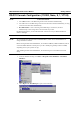
EDS-408A/405A Series User’s Manual EDS Configurator GUI Starting EDS Configurator To start EDS Configurator, locate and then run the executable file edscfgui.exe. NOTE You may download the EDS Configurator software from Moxa’s website at www.moxa.com. For example, if the file was placed on the Windows desktop, it should appear as follows. Double click the icon to run the program. The Moxa EtherDevice Server Configurator window will open, as shown.
EDS-408A/405A Series User’s Manual EDS Configurator GUI Once the search is complete, the Configurator window will display a list of all switches that were located. Search by IP address This utility is used to search for EDSs one at a time. Note that the search is conducted by IP address, so you should be able to locate any EDS that is properly connected to your LAN, WAN, or even the Internet. Start by clicking the Specify by IP address icon , or by selecting Specify IP address from the List Server menu.
EDS-408A/405A Series User’s Manual 4. EDS Configurator GUI Click Open to navigate to the folder that contains the firmware upgrade file, and then click the correct “*.rom” file (eds.rom in the example shown below) to select the file. Click Open to activate the upgrade process. Modify IP Address You may use the Modify IP Address function to reconfigure the EDS’s network settings. Start by clicking the Modify IP address icon , or by selecting Modify IP address from the Configuration menu.
EDS-408A/405A Series User’s Manual EDS Configurator GUI Export Configuration The Export Configuration utility is used to save the entire configuration of a particular EDS to a text file. Do the following to export a configuration: 1. Highlight the switch (from the Server list in the Configurator window’s left pane), and then click the Export toolbar icon or select Export Configuration from the Configuration menu.
EDS-408A/405A Series User’s Manual EDS Configurator GUI Import Configuration The Import Configuration function is used to import an entire configuration from a text file to the EDS. This utility can be used to transfer the configuration from one EDS to another, by first using the Export Configuration function (described in the previous section) to save a switch configuration to a file, and then using the Import Configuration function. Do the following to import a configuration: 1.
EDS-408A/405A Series User’s Manual 4. EDS Configurator GUI Click Yes in response to the following warning message to accept the new settings. Unlock Server The Unlock Server function is used to open a password protected switch so that the user can modify its configuration, import/export a configuration, etc. There are six possible responses under the Status column.
EDS-408A/405A Series User’s Manual EDS Configurator GUI 2. When the Unlock status window reports Progress as OK, click the Close button on the upper right corner of the window. 3. The status of the switch will now read either Unlocked or Unlocked Fixed.
A Appendix A MIB Groups Moxa EtherDevice Switches come with built-in SNMP (Simple Network Management Protocol) agent software that supports cold/warm start trap, line up/down trap, and RFC 1213 MIB-II. The standard MIB groups that the EDS-408A/405A support are: MIB II.1 – System Group MIB II.2 – Interfaces Group MIB II.4 – IP Group MIB II.5 – ICMP Group MIB II.6 – TCP Group MIB II.7 – UDP Group MIB II.10 – Transmission Group MIB II.11 – SNMP Group MIB II.16 – RMON MIB II.17 – Dot1dBridge Group MIB II.17.
B Appendix B Specifications Technology Standards Protocols IEEE802.3, 802.3u, 802.3x, 802.1D, 802.1w, 802.1p SNMP V1/V2c/V3, DHCP Server/Client, BootP, RMON, TFTP, SNTP, SMTP, RARP and EDS-SNMP OPC server Pro (Optional) MIB MIB-II, Ethernet-Like MIB, P-BRIDGE MIB, RMON MIB Group 1, 2, 3, 9, MIB, Bridge MIB, RSTP MIB Forwarding and Filtering Rate 148810 pps Processing Type Store and Forward Flow Control IEEE802.
EDS-408A/405A Series User’s Manual Mechanical Dimensions Weight Installation Casing Environment Operating Temperature Storage Temperature Ambient Relative Humidity Regulatory Approvals Safety Hazardous Location Maritime EMI EMS Shock Freefall Vibration WARRANTY Specifications 53.6 × 135 × 105 mm (W × H × D) 0.