CSM-200 Series Hardware Installation Guide First Edition, November 2009 © 2009 Moxa Inc. All rights reserved. Reproduction without permission is prohibited. Fl.4, No.135, Lane 235, Pao-Chiao Rd. Shing Tien City, Taipei, Taiwan, R.O.C.
Overview Introduction The CSM-200 series is an Ethernet to optical fiber media converter and is part of the NRack System. It provides Ethernet media conversion from 10/100 BaseT(X) to 100 BaseFX (SC or ST connectors), and can be installed in every chassis of the NRack System. The CSM-200 Series includes the following models: • • • CSM-200-1213: 10/100BaseT(X) to 100BaseFX slide-in module media converter, multi-mode ST connector.
Features y LFP(Link Fault Pass-through) and FEF(Far End Fault) y Two different operation modes ¾ Store-and-Forward ¾ Pass Through y Auto negotiation y Support TS-1000 ver. 2 y Support Turbo Ring 2 y Plug and Play y Hot-swap Package Checklist Moxa’s CSM-200 Series is shipped with the following items. If any of these items is missing or damaged, please contact your customer service representative for assistance.
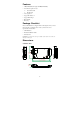
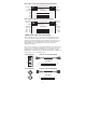
CSM-200-1214/CSM-200-1218 PWR Fiber Link TX RX 86.8 mm (3.42 in) 10M 100M 117.1 mm (4.61 in) 124.3 mm (4.89 in) 21 mm (0.83 in) ATTENTION Electrostatic Discharge Warning! To protect the product from damage due to electrostatic discharge, we recommend wearing a grounding device when handling your CSM-200 slide-in modules. Communication Connections The CSM-200 Series has one 10/100BaseT(X) Ethernet port, and one 100BaseFX (SC or ST type connector) fiber port.
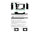
RJ45 (8-pin) to RJ45 (8-pin) Straight-Through Cable Wiring Straight-Through Cable Switch Port NIC Port RJ45 Plug Pin 1 RJ45 Connector RJ45 Connector Cable Wiring Tx+ TxRx+ Rx- 3 6 1 2 3 6 1 2 Rx+ RxTx+ Tx- RJ45 (8-pin) to RJ45 (8-pin) Cross-Over Cable Wiring Cross-Over Cable Switch Port (NIC Port) RJ45 Plug Pin 1 RJ45 Connector (Rx+) (Rx-) (Tx+) (Tx-) Tx+ TxRx+ Rx- Switch Port (NIC Port) RJ45 Connector Cable Wiring 3 6 1 2 1 2 3 6 (Tx+) (Tx-) (Rx+) (Rx-) Rx+ RxTx+ Tx- 100BaseFX Fiber Po
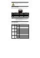
ATTENTION This is a Class 1 Laser/LED product. Do not stare into the Laser Beam. Switch Settings There is 1 set of DIP switches on the board. The following figure and table give the settings for the 5-connector DIP switch. DIP 1 2 3 4 5 Function Auto Negotiation Force TP Speed Force TP Duplex Link Fault Pass Through Operating Mode NOTE 1. 2. ON Enable 100 M Full Duplex Enable Store-and-Forward OFF Disable 10 M Half Duplex Disable Pass Through All the DIP settings default to “ON”.
Auto MDI/MDI-X Connection The Auto MDI/MDI-X function allows users to connect the Moxa CSM-200’s 10/100BaseTX ports to any kind of Ethernet device, without needing to determine the type of Ethernet cable being used for the connection. This means that you can use either a straight-through cable or cross-over cable to connect the CSM-200 Series to Ethernet devices.
Specifications Technology Standards IEEE 802.3 for 10BaseT, IEEE 802.3u for 100BaseT(X), 100BaseFX Interface RJ45 ports 10/100BaseT(X) Fiber ports 100BaseFX (SC/ST connector) LED Indicators PWR, Fiber Link, 10/100M(TP port) Optical Fiber 100BaseFX Multi-mode Single-mode Wavelength Max. TX Min. TX RX Sensitivity Link Budget 1300 nm 1310 nm -10 dBm 0 dBm -20 dBm -5 dBm -32 dBm -34 dBm 12 dB 29 dB 5 km a Typical Distance 40 km c 4 km b Saturation -6 dBm -3 dBm a.
EMS EN61000-4-2 (ESD), Criteria A, Level 4 EN61000-4-3 (RS), Criteria A, Level 2 EN61000-4-4 (EFT), Criteria A, Level 3 EN61000-4-5 (Surge), Criteria A, Level 3 EN61000-4-6 (CS), Criteria A, Level 2 En61000-4-8 (PFMF), Criteria A, Level 3 Freefall IEC 60068-2-32 Warranty Warranty Period 5 years Details: See www.moxa.com/warranty Technical Support Contact Information www.moxa.