Moxa Managed Ethernet Switch/Extender User’s Manual Sixth Edition, September 2013 www.moxa.com/product © 2013 Moxa Inc. All rights reserved.
Moxa Managed Ethernet Switch/Extender User’s Manual The software described in this manual is furnished under a license agreement and may be used only in accordance with the terms of that agreement. Copyright Notice © 2013 Moxa Inc., All rights reserved. Trademarks The MOXA logo is a registered trademark of Moxa Inc. All other trademarks or registered marks in this manual belong to their respective manufacturers.
Table of Contents 1. About this Manual ............................................................................................................................. 1-1 2. Getting Started.................................................................................................................................. 2-1 Serial Console Configuration (115200, None, 8, 1, VT100) ....................................................................... 2-2 Configuration by Telnet Console ......................
Using Diagnosis ................................................................................................................................ 3-73 Mirror Port ................................................................................................................................ 3-73 Ping ......................................................................................................................................... 3-74 LLDP Function ......................................................
1 1. About this Manual Thank you for purchasing a Moxa managed Ethernet switch. Read this user’s manual to learn how to connect your Moxa switch to Ethernet-enabled devices used for industrial applications. The following two chapters are covered in this user manual: Getting Started This chapter explains how the initial installation process for Moxa switch. There are three ways to access Moxa switch's configuration settings: the serial console, Telnet console, and web console.
2 2. Getting Started In this chapter we explain how to install a Moxa switch for the first time. There are three ways to access the Moxa switch’s configuration settings: serial console, Telnet console, or web console. If you do not know the Moxa switch’s IP address, you can open the serial console by connecting the Moxa switch to a PC’s COM port with a short serial cable. You can open the Telnet or web console over an Ethernet LAN or over the Internet.
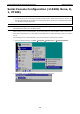
Moxa Managed Ethernet Switch/Extender Getting Started Serial Console Configuration (115200, None, 8, 1, VT100) NOTE • You cannot connect to the serial and Telnet console at the same time. • You can connect to the web console and another console (serial or Telnet) at the same time. However, we strongly recommend that you do NOT do so. Following this advice will allow you to maintain better control over the Moxa switch’s configuration.
Moxa Managed Ethernet Switch/Extender Getting Started 3. The Property window should open. On the Communication Parameter tab for Ports, select the COM port that is being used for the console connection. Set the other fields as follows: 115200 for Baud Rate, 8 for Data Bits, None for Parity, and 1 for Stop Bits. 4. On the Terminal tab, select VT100 for Terminal Type, and then click OK to continue. 5. In the terminal window, the Moxa switch will prompt you to select a terminal type.
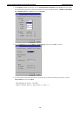
Moxa Managed Ethernet Switch/Extender Getting Started 6. The serial console will prompt you to log in. Press Enter and select admin or user. Use the down arrow key on your keyboard to select the Password field and enter a password if desired. This password will be required to access any of the consoles (web, serial, Telnet). If you do not wish to create a password, leave the Password field blank and press Enter. 7. The Main Menu of the Moxa switch’s serial console should appear.
Moxa Managed Ethernet Switch/Extender NOTE Getting Started To connect to the Moxa switch’s Telnet or web console, your PC host and the Moxa switch must be on the same logical subnet. NOTE When connecting to the Moxa switch’s Telnet or web console, first connect one of the Moxa switch’s Ethernet ports to your Ethernet LAN, or directly to your PC’s Ethernet port. You may use either a straight-through or cross-over Ethernet cable. NOTE The Moxa switch’s default IP address is 192.168.127.253.
Moxa Managed Ethernet Switch/Extender Getting Started 4. The Main Menu of the Moxa switch’s Telnet console should appear. 5. In the terminal window, select Preferences… from the Terminal menu on the menu bar. 6. The Terminal Preferences window should appear. Make sure that VT100 Arrows is checked. 7.
Moxa Managed Ethernet Switch/Extender NOTE Getting Started When connecting to the Moxa switch’s Telnet or web console, first connect one of the Moxa switch’s Ethernet ports to your Ethernet LAN, or directly to your PC’s Ethernet port. You may use either a straight-through or cross-over Ethernet cable. NOTE The Moxa switch’s default IP address is 192.168.127.253.
Moxa Managed Ethernet Switch/Extender Getting Started Disabling Telnet and Browser Access If you are connecting the Moxa switch to a public network but do not intend to manage it over the network, we suggest disabling both the Telnet and web consoles. This is done from the serial console by navigating to System Identification under Basic Settings.
3 3. Featured Functions In this chapter, we explain how to access the Moxa switch’s various configuration, monitoring, and administration functions. These functions can be accessed by serial, Telnet, or web console. The serial console can be used if you do not know the Moxa switch’s IP address and requires that you connect the Moxa switch to a PC COM port. The Telnet and web consoles can be opened over an Ethernet LAN or the Internet.
Moxa Managed Ethernet Switch/Extender Featured Functions Configuring Basic Settings The Basic Settings section includes the most common settings required by administrators to maintain and control a Moxa switch. System Identification System Identification items are displayed at the top of the web console and will be included in alarm emails. You can configure the System Identification items to make it easier to identify different switches that are connected to your network.
Moxa Managed Ethernet Switch/Extender Featured Functions Web Auto-logout (S) Setting Description Factory Default 60 to 86400 (seconds) Disable or extend the auto-logout time for the web 0 (disabled) management console. Age Time (S) Setting Description 15 to 3825 (seconds) The length of time that a MAC address entry can remain in the 300 Factory Default Moxa switch.
Moxa Managed Ethernet Switch/Extender Featured Functions Account Setting Description Factory Default Admin This account can modify the Moxa switch’s configuration. admin User This account can only view the Moxa switch’s configurations. Password Setting Description Factory Default Old password Enter the current password None (max. 16 characters) New password Enter the desired new password. Leave it blank if you want to None (Max. 16 characters) remove the password. Retype password (Max.
Moxa Managed Ethernet Switch/Extender Featured Functions Port Settings Ethernet Port Settings Port settings are included to give the user control over port access, port transmission speed, flow control, and port type (MDI or MDIX). Enable Setting Description Factory Default Checked Allows data transmission through the port. Enabled Unchecked Immediately shuts off port access.
Moxa Managed Ethernet Switch/Extender Featured Functions FDX Flow Ctrl This setting enables or disables flow control for the port when the port’s Speed is set to Auto. The final result will be determined by the Auto process between the Moxa switch and connected devices. Setting Enable Disable Description Factory Default Enables flow control for this port when the port’s Speed is set to Auto. Disables flow control for this port when the port’s Speed Disabled is set to Auto.
Moxa Managed Ethernet Switch/Extender Featured Functions In standard mode, the connection speed is decided once the connection is established between the CO and the CPE based on signal-to-noise ratio (SNR). However, the transmission speed will be auto detected from 5696Kbps to 15.3Mbps. It should take less than 5 minutes to complete the training process.
Moxa Managed Ethernet Switch/Extender Featured Functions Link Fault Pass-Through (IEX series only) If the Ethernet or DSL connection is down, the device will not be notified that the connection has been terminated. The device will continue to transmit packets and wait idly for a response that never arrives—and the longer the wait, the higher the possibility that packets will be lost.
Moxa Managed Ethernet Switch/Extender Featured Functions IP4 The IPv4 settings include the switch’s IP address and subnet mask, as well as the IP address of the default gateway. In addition, input cells are provided for the IP addresses of a 1st and 2nd DNS server. Auto IP Configuration Setting Description Factory Default Disable The Moxa switch’s IP address must be set manually. Disable By DHCP The Moxa switch’s IP address will be assigned automatically by the network’s DHCP server.
Moxa Managed Ethernet Switch/Extender Featured Functions Global Unicast Address Prefix (Prefix Length: 64 bits) Default Gateway Setting Description Global Unicast Address The prefix value must be formatted according to the RFC 2373 None Prefix Factory Default “IPv6 Addressing Architecture,” using 8 colon-separated 16-bit hexadecimal values. One double colon may be used in the address to indicate the appropriate number of zeros required to fill the undefined fields.
Moxa Managed Ethernet Switch/Extender NOTE Featured Functions Leave Time should be at least two times more than Join Time, and Leaveall Time should be larger than Leave Time. System Time Settings The Moxa switch has a time calibration function based on information from an NTP server or user specified time and date. Functions such as automatic warning emails can therefore include time and date stamp. NOTE The Moxa switch does not have a real time clock.
Moxa Managed Ethernet Switch/Extender Featured Functions Time Zone NOTE Setting Description Factory Default Time zone Specifies the time zone, which is used to determine the local GMT (Greenwich time offset from GMT (Greenwich Mean Time). Mean Time) Changing the time zone will automatically correct the current time. Be sure to set the time zone before setting the time. Time Server IP/Name Setting Description Factory Default IP address or name of The IP or domain address (e.g., 192.168.1.
Moxa Managed Ethernet Switch/Extender Featured Functions 1. The Boundary Clock and Transparent Clock functionalities defined by IEEE 1588 must be implemented in the switch. 2. The switch must be configured such that it does not pass IEEE 1588 message traffic using the normal communication mechanisms of the switch. Such an Ethernet switch will synchronize clocks directly connected to one of its ports to the highest possible accuracy.
Moxa Managed Ethernet Switch/Extender Featured Functions Configuring PTP 3-14
Moxa Managed Ethernet Switch/Extender Featured Functions IEEE 1588/PTP Operation Operation Setting Description Factory Default Enable PTP Globally disables or enables IEEE 1588 operation. Disabled IEEE 1588/PTP Configuration Clock Mode (sets the switch’s clock mode) Setting Description Factory Default v1 BC Operates as an IEEE 1588 v1 boundary clock. v1 BC v2 E2E 2-step TC Operates as an edge-to-edge IEEE 1588 v2 transparent clock with 2-step method.
Moxa Managed Ethernet Switch/Extender Featured Functions Preferred Master Setting Description Factory Default True or False Set this switch to be the Grand Master. False Setting Description Factory Default 0 to 255 Set first priority value; 0 = highest priority, 255 = lowest 128 priority1 priority. priority2 Setting Description Factory Default 0 to 255 Set second priority value; 0 = highest priority, 255 = lowest 128 priority.
Moxa Managed Ethernet Switch/Extender Featured Functions UTC Offset Setting Description Factory Default 0 to 255 The known UTC offset (seconds). 0 Setting Description Factory Default N/A Shows the current IEEE 1588 PTP status. N/A Status PTP Port Settings Shows the current switch PTP port settings. System File Update Update System Files by Remote TFTP The Moxa switch supports saving your configuration or log file to a remote TFTP server or local host.
Moxa Managed Ethernet Switch/Extender Featured Functions Update System Files from Local PC Configuration File Click Export to save the Moxa switch’s configuration file to the local host. Log File Click Export to save the Moxa switch’s log file to the local host. NOTE Some operating systems will open the configuration file and log file directly in the web page. In such cases, right click the Export button to save the file.
Moxa Managed Ethernet Switch/Extender Featured Functions Restart This function provides users with a quick way to restart the system. Reset to Factory Default This function provides users with a quick way of restoring the Moxa switch’s configuration to factory defaults. The function is available in the serial, Telnet, and web consoles.
Moxa Managed Ethernet Switch/Extender Featured Functions To avoid broadcast storms or loops in your network while configuring a trunk, first disable or disconnect all ports that you want to add to the trunk or remove from the trunk. After you finish configuring the trunk, enable or re-connect the ports. If all ports on both switch units are configured as 100BaseTX and they are operating in full duplex mode, the potential bandwidth of the connection will be up to 1.6 Gbps.
Moxa Managed Ethernet Switch/Extender Featured Functions Trunk Type Setting Description Factory Default Static Selects Moxa’s proprietary trunking protocol. Static LACP Selects LACP (IEEE 802.3ad, Link Aggregation Control Static Protocol). Available Ports/Member Ports Setting Description Member/Available Lists the ports in the current trunk group and the ports that are N/A Factory Default ports available to be added. Check box Selects the port to be added or removed from the group.
Moxa Managed Ethernet Switch/Extender V2c Featured Functions Community V1, V2c authentication. Community string No Write/Read Uses a community string match for authentication. Community SNMP V3 No-Auth No No MD5 or SHA Authentication No Uses an account with admin or user to access objects Provides authentication based on HMAC-MD5, based on MD5 or or HMAC-SHA algorithms. 8-character SHA passwords are the minimum requirement for authentication.
Moxa Managed Ethernet Switch/Extender V1, V2c, V3, or Featured Functions Specifies the SNMP protocol version used to manage the switch. V1, V2c V1, V2c, or V3 only V1, V2c Read Community Setting Description Max. 30 characters Specifies the community string to authenticate the SNMP agent Public Factory Default for read-only access. The SNMP agent will access all objects with read-only permissions using this community string. V1, V2c Write/Read Community Setting Description Max.
Moxa Managed Ethernet Switch/Extender Featured Functions Trap Settings SNMP traps allow an SNMP agent to notify the NMS of a significant event. The switch supports two SNMP modes, Trap mode and Inform mode. SNMP Trap Mode—Trap In Trap mode, the SNMP agent sends an SNMPv1 trap PDU to the NMS. No acknowledgment is sent back from the NMS so the agent has no way of knowing if the trap reached the NMS. SNMP Trap Mode—Inform SNMPv2 provides an inform mechanism.
Moxa Managed Ethernet Switch/Extender Featured Functions Using PoE (PoE Models Only) Power over Ethernet has become increasingly popular due in large part to the reliability provided by PoE Ethernet switches that supply the necessary power to Powered Devices (PD) when AC power is not readily available or cost-prohibitive to provide locally.
Moxa Managed Ethernet Switch/Extender Featured Functions Port Setting Enable Setting Description Factory Default Checked Allows data and power transmission through the port Enable Unchecked Immediately shuts off port access Enable Setting Description Factory Default Auto The amount of power assigned is determined according to the Auto Power Limit class that is read from the powered device.
Moxa Managed Ethernet Switch/Extender Featured Functions Checked Enables the port for a defined number of days Unchecked Disables the port for a defined number of days Disable Start/End Time Setting Description Factory Default Time for working period Allows users to enter the start and end time for the PD’s 0-24 working period PoE Status Item Description Enable/Disable Indicates the PoE port status Consumption (W) Indicates the actual Power consumed value for PoE port Voltage (V) Indica
Moxa Managed Ethernet Switch/Extender Featured Functions Port Events Warning e-mail is sent when... Power-Fail When actual PD power consumption exceeds related PD power limit settings. PD-Failure When the switch cannot receive a PD response after the defined period. Type 2 PoE Setting The setting are included to give the user control over the system’s PoE power output, PoE power threshold, PoE port configuration, and PD failure check.
Moxa Managed Ethernet Switch/Extender Featured Functions Enable Enables power transmission to PD Disable Disables power transmission to PD Enable PoE power threshold Setting Description Factory Default 30 to 240 Set the threshold of total PoE power output 240 PoE threshold cutoff Setting Description Factory Default Enable Cutoff the PD’s power while its over the threshold Disable Disable No cutoff while the PD’s power over the threshold Sum of allocated power Setting Description Alloc
Moxa Managed Ethernet Switch/Extender Featured Functions Legacy PD Detection The PoE Ethernet Switch provides the Legacy PD Detection function. When the capacitance of PD is higher than 2.7μF, checking the Legacy PD Detection enables system to output power to PD. If you check the Legacy PD Detection, it will take longer detection time from 10 to 15 seconds before PoE power output.
Moxa Managed Ethernet Switch/Extender Featured Functions Port Setting Description Factory Default Port Enable a dedicated port Port 1 Enable Setting Description Factory Default Checked Enables the port for a defined time period Disable Unchecked Disables the port for a defined time period Weekly Timetabling Day Setting Description Factory Default Checked Enables the port for a defined number of days Disable Unchecked Disables the port for a defined number of days Start/End Time Setti
Moxa Managed Ethernet Switch/Extender Featured Functions Enable Enables the SNMP trap function of PoE warning Disable Disables the SNMP trap function of PoE warning Disable Relay Output Setting Description Factory Default Enable Enables the relay output function of PoE warning Disable Disable Disables the relay output function of PoE warning Email Setting Description Factory Default Enable Enables the email alarm function of PoE warning Disable Disable Disables the email alarm function
Moxa Managed Ethernet Switch/Extender Featured Functions PoE Diagnose PoE Diagnose helps users to figure out the PD conditions, and the system provides users configuration suggestions to select the best setting for the PDs.
Moxa Managed Ethernet Switch/Extender Featured Functions PoE Port Configuration Suggestion Item Description Disable PoE power output When detecting an NIC or unknown PD, the system suggests disabling PoE power output. Enable “Legacy PD Detection” When detecting a higher capacitance of PD, the system suggests enabling Legacy PD Detection. Select Force Mode When detecting higher/lower resistance or higher capacitance, the system suggests selecting Force Mode. Select IEEE 802.
Moxa Managed Ethernet Switch/Extender Featured Functions PoE Port Status Status Description Item Description Not Present No connection to the port. No PoE power outputs. Powered PoE power outputs from the PSE NIC System detects an NIC connected to the port. No PoE power outputs. Disabled The PoE function of the port is disabled. No PoE power outputs. Fault In Force mode, system detects a out-of-range PD Legacy Powered In Force mode, system detects a Legacy PD In 802.
Moxa Managed Ethernet Switch/Extender Featured Functions System Power Status System power status allows users to view a graph which includes Sum of measured power, Sum of allocated power, and Max of allocated power. Sum of measured power (in pink color) indicates total measured power of PDs, Sum of allocated power (in blue color) indicates total allocated power, and Max of allocated power (in red color) indicates the threshold of total PoE power output.
Moxa Managed Ethernet Switch/Extender Featured Functions 4 Controlled Load (streaming multimedia) 5 Video (interactive media); less than 100 milliseconds of latency and jitter 6 Voice (interactive voice); less than 10 milliseconds of latency and jitter 7 Network Control Reserved traffic Even though the IEEE 802.
Moxa Managed Ethernet Switch/Extender • Featured Functions Weight Fair: This method services all the traffic queues, giving priority to the higher priority queues. Under most circumstances, the Weight Fair method gives high priority precedence over low priority, but in the event that high priority traffic does not reach the link capacity, lower priority traffic is not blocked.
Moxa Managed Ethernet Switch/Extender Featured Functions Queuing Mechanism Setting Description Factory Default Weight Fair The Moxa switch has 4 priority queues. In the weight fair Weight Fair scheme, an 8, 4, 2, 1 weighting is applied to the four priorities. This approach prevents the lower priority frames from being starved of opportunity for transmission with only a slight delay to the higher priority frames.
Moxa Managed Ethernet Switch/Extender Featured Functions Type 2 Queuing Mechanism Setting Description Factory Default Weight Fair The Moxa switch has 4 priority queues. In the weight fair Weight Fair scheme, an 8, 4, 2, 1 weighting is applied to the four priorities. This approach prevents the lower priority frames from being starved of opportunity for transmission with only a slight delay to the higher priority frames.
Moxa Managed Ethernet Switch/Extender Featured Functions CoS Mapping CoS Value and Priority Queues Setting Description Factory Default Low/Normal/ Maps different CoS values to 4 different egress queues. 0: Low Medium/High 1: Low 2: Normal 3: Normal 4: Medium 5: Medium 6: High 7: High TOS/DiffServ Mapping ToS (DSCP) Value and Priority Queues Setting Description Factory Default Low/Normal/ Maps different TOS values to 4 different egress queues.
Moxa Managed Ethernet Switch/Extender Featured Functions Using Virtual LAN Setting up Virtual LANs (VLANs) on your Moxa switch increases the efficiency of your network by dividing the LAN into logical segments, as opposed to physical segments. In general, VLANs are easier to manage. The Virtual LAN (VLAN) Concept What is a VLAN? A VLAN is a group of devices that can be located anywhere on a network, but which communicate as if they are on the same physical segment.
Moxa Managed Ethernet Switch/Extender Featured Functions VLANs and the Rackmount switch Your Moxa switch provides support for VLANs using IEEE Std 802.1Q-1998. This standard allows traffic from multiple VLANs to be carried across one physical link. The IEEE Std 802.1Q-1998 standard allows each port on your Moxa switch to be placed as follows: • On a single VLAN defined in the Moxa switch • On several VLANs simultaneously using 802.1Q tagging The standard requires that you define the 802.
Moxa Managed Ethernet Switch/Extender Featured Functions Sample Applications of VLANs Using Moxa Switches In this application, • Port 1 connects a single untagged device and assigns it to VLAN 5; it should be configured as Access Port with PVID 5. • Port 2 connects a LAN with two untagged devices belonging to VLAN 2. One tagged device with VID 3 and one tagged device with VID 4.
Moxa Managed Ethernet Switch/Extender Featured Functions Configuring Virtual LAN VLAN Settings To configure 802.1Q VLAN and port-based VLANs on the Moxa switch, use the VLAN Settings page to configure the ports. VLAN Mode NOTE Setting Description Factory Default 802.1Q VLAN Set VLAN mode to 802.1Q VLAN 802.1Q VLAN Port-based VLAN Set VLAN mode to Port-based VLAN Unaware VLAN Set VLAN mode to Unaware VLAN Only EDS-728 and IKS-6726/6728 provides the Unaware VLAN function. 802.
Moxa Managed Ethernet Switch/Extender Featured Functions Port PVID Setting Description VID ranges from 1 to Sets the default VLAN ID for untagged devices that connect to 1 Factory Default 4094 the port. Fixed VLAN List (Tagged) Setting Description VID ranges from 1 to This field will be active only when selecting the Trunk or Hybrid None Factory Default 4094 port type. Set the other VLAN ID for tagged devices that connect to the port. Use commas to separate different VIDs.
Moxa Managed Ethernet Switch/Extender Featured Functions Unaware VLAN Settings The Unaware VLAN function provides users a flexible operation in a VLAN network. Switches which are set on Unaware VLAN mode do not check the VLAN tags of input Ethernet frame. All of VLAN tags can always in and out of the Unaware VLAN switch, and the switch won’t affect the VLAN tags of Ethernet frames. NOTE When users enable Unaware VLAN function, all of ports are set as unaware VLAN ports.
Moxa Managed Ethernet Switch/Extender Featured Functions VLAN Table Use the 802.1Q VLAN table to review the VLAN groups that were created, Joined Access Ports, Trunk Ports, and Hybrid Ports, and use the Port-based VLAN table to review the VLAN group and Joined Ports. NOTE Most Moxa managed switches have a maximum of 64 VLAN settings. However, the IKS-G6524/G6824 and ICS-G7000 series support up to 256 VLAN settings.
Moxa Managed Ethernet Switch/Extender Featured Functions Multicast transmission makes more sense and is more efficient than unicast transmission for some applications. For example, multicasts are often used for video-conferencing, since high volumes of traffic must be sent to several end-stations at the same time, but where broadcasting the traffic to all end-stations would cause a substantial reduction in network performance.
Moxa Managed Ethernet Switch/Extender Featured Functions Snooping Mode Snooping Mode allows your switch to forward multicast packets only to the appropriate ports. The switch snoops on exchanges between hosts and an IGMP device, such as a router, to find those ports that want to join a multicast group, and then configures its filters accordingly. IGMP Snooping Enhanced Mode Snooping Enhanced Mode allows your switch to forward multicast packets to the Moxa switch’s member port only.
Moxa Managed Ethernet Switch/Extender Featured Functions GMRP (GARP Multicast Registration Protocol) Moxa switches support IEEE 802.1D-1998 GMRP (GARP Multicast Registration Protocol), which is different from IGMP (Internet Group Management Protocol). GMRP is a MAC-based multicast management protocol, whereas IGMP is IP-based. GMRP provides a mechanism that allows bridges and end stations to register or de-register Group membership information dynamically.
Moxa Managed Ethernet Switch/Extender Featured Functions IGMP Snooping Enable Setting Description Factory Default Enable/Disable Checkmark the IGMP Snooping Enable checkbox near the Disabled top of the window to enable the IGMP Snooping function globally. NOTE: You should enable IGMP Snooping if the network also uses non-Moxa 3rd party switches. Query Interval Setting Description Factory Default Numerical value, input Sets the query interval of the Querier function globally.
Moxa Managed Ethernet Switch/Extender Featured Functions Layer 2 switch page Layer 3 switch page The information shown in the table includes: • Auto-learned Multicast Router Port: This indicates that a multicast router connects to/sends packets from • Static Multicast Router Port: Displays the static multicast querier port(s) • Querier Connected Port: Displays the port which is connected to the querier. • Act as a Querier: Displays whether or not this VLAN is a querier (winner of a election).
Moxa Managed Ethernet Switch/Extender NOTE Featured Functions The IGMP stream table is supported only in Layer 3 switches Static Multicast MAC Addresses Layer 2 switch page Layer 3 switch page NOTE: 01:00:5E:XX:XX:XX on this page is the IP multicast MAC address. Please activate IGMP Snooping for automatic classification. Add New Static Multicast Address to the List Setting Description Factory Default MAC Address Input the multicast MAC address of this host.
Moxa Managed Ethernet Switch/Extender Featured Functions Join Port Setting Description Select/Deselect Checkmark the appropriate check boxes to select the join ports None Factory Default for this multicast group. Configuring GMRP GMRP is a MAC-based multicast management protocol, whereas IGMP is IP-based. GMRP provides a mechanism that allows bridges and end stations to register or un-register Group membership information dynamically.
Moxa Managed Ethernet Switch/Extender Featured Functions Multicast Filtering Behavior Setting Description Factory Default Multicast Filtering Define the multicast filtering behavior by three options: Forward Unknown Behavior Forward All: flood all multicast packets to the VLAN of the network. Forward Unknown: flood unknown multicast packets to the VLAN while known multicast packets are sent to the indicated groups.
Moxa Managed Ethernet Switch/Extender Featured Functions Type 1 Traffic Rate Limiting Settings Control Mode Description Factory Default Normal Set the max. ingress rate limit for different packet types Port Disable When the ingress multicast and broadcast packets exceed the ingress rate limit, the port will be disabled for a certain period. Normal During this period, all packets from this port will be discarded.
Moxa Managed Ethernet Switch/Extender Featured Functions Egress Rate Limit Setting Description Egress rate Select the ingress rate limit (% of max.
Moxa Managed Ethernet Switch/Extender Featured Functions Ingress and Egress Rate Limit - Normal Setting Description Factory Default Ingress rate Select the ingress/egress rate limit (% of max.
Moxa Managed Ethernet Switch/Extender Featured Functions Security NOTE: Security functions not supported in EDS-400A series. Security can be categorized in two levels: the user name/password level, and the port access level. For user name/password level security, Moxa switches provide two different user login options: Terminal Access Controller Access-Control System Plus (TACACS+) and Remote Authentication Dial In User Service (RADIUS).
Moxa Managed Ethernet Switch/Extender Featured Functions Using Port Access Control The Moxa switch provides two kinds of Port-Based Access Control: Static Port Lock and IEEE 802.1X. Static Port Lock In this case, the Moxa switch can also be configured to protect static MAC addresses for a specific port. With the Port Lock function, these locked ports will not learn any additional addresses, but only allow traffic from preset static MAC addresses, helping to block hackers and careless usage. IEEE 802.
Moxa Managed Ethernet Switch/Extender Featured Functions Configuring IEEE 802.1X Database Option Setting Description Factory Default Local Select this option when setting the Local User Database as the Local (Max. of 32 users) authentication database. Radius Select this option to set an external RADIUS server as the Local authentication database. The authentication mechanism is EAP-MD5.
Moxa Managed Ethernet Switch/Extender Featured Functions 802.1X Setting Description Factory Default Enable/Disable Checkmark the checkbox under the 802.1X column to enable Disable IEEE 802.1X for one or more ports. All end stations must enter usernames and passwords before access to these ports is allowed. 802.1X Re-Authentication The Moxa switch can force connected devices to be re-authorized manually. 802.
Moxa Managed Ethernet Switch/Extender Featured Functions Dot1X Radius Server Setting Same as Auth Server Setting Setting Description Factory Default Enable/Disable Enable to use the same setting as Auth Server Disable Setting Description Factory Default Server IP/Name Specifies the IP/name of the server localhost Server Port Specifies the port of the server 1812 Server Shared Key Specifies the shared key of the server None Server Setting Port Access Control Table The port status will
Moxa Managed Ethernet Switch/Extender Featured Functions Configure Email Event Types Select the desired Event types from the Console or Web Browser Event type page (a description of each event type is given later in the Email Alarm Events setting subsection).
Moxa Managed Ethernet Switch/Extender NOTE Featured Functions The Traffic-Overload, Traffic-Threshold (%), and Traffic-Duration (sec.) Port Event items are related. If you Enable the Traffic-Overload event, then be sure to enter a nonzero Traffic-Threshold percentage, as well as a Traffic-Duration between 1 and 300 seconds.
Moxa Managed Ethernet Switch/Extender Featured Functions Email Address Setting Description Factory Default Max. of 30 characters You can set up to 4 email addresses to receive alarm emails None from the Moxa switch. Send Test Email After you complete the email settings, you should first click Activate to activate those settings, and then press the Send Test Email button to verify that the settings are correct.
Moxa Managed Ethernet Switch/Extender Featured Functions The Moxa switch supports two relay outputs. You can configure which relay output is related to which events, which helps administrators identify the importance of the different events.
Moxa Managed Ethernet Switch/Extender Featured Functions Configuring Line-Swap Fast Recovery Enable Line-Swap-Fast-Recovery Setting Description Factory Default Enable/Disable Checkmark the checkbox to enable the Enable Line-Swap-Fast-Recovery function Using Set Device IP To reduce the effort required to set up IP addresses, the Moxa switch comes equipped with DHCP/BootP server and RARP protocol to set up IP addresses of Ethernet-enabled devices automatically.
Moxa Managed Ethernet Switch/Extender Featured Functions Configuring Set Device IP Automatic “Set Device IP” by DHCP/BootP/RARP Desired IP Address Setting Description Factory Default IP Address Set the desired IP of connected devices. None Option 82 is used by the relay agent to insert additional information into the client’s DHCP request. The Relay Agent Information option is inserted by the DHCP relay agent when forwarding client-originated DHCP packets to a DHCP server.
Moxa Managed Ethernet Switch/Extender Featured Functions Configuring DHCP Relay Agent 3-71
Moxa Managed Ethernet Switch/Extender Featured Functions Server IP Address 1st Server Setting Description IP address for the 1st Assigns the IP address of the 1st DHCP server that the switch None Factory Default DHCP server tries to access. 2nd Server Setting Description Factory Default IP address for the 2nd Assigns the IP address of the 2nd DHCP server that the switch None DHCP server tries to access.
Moxa Managed Ethernet Switch/Extender Featured Functions Using Diagnosis The Moxa switch provides three important tools for administrators to diagnose network systems. Mirror Port The Mirror Port function can be used to monitor data being transmitted through a specific port. This is done by setting up another port (the mirror port) to receive the same data being transmitted from, or both to and from, the port under observation.
Moxa Managed Ethernet Switch/Extender Featured Functions Type 2 Mirror Port Settings Setting Description Monitored Port Select the number of one port whose network activity will be monitored. Watch Direction Select one of the following two watch direction options: Input data stream: Select this option to monitor only those data packets coming into the Moxa switch’s port. Output data stream: Select this option to monitor only those data packets being sent out through the Moxa switch’s port.
Moxa Managed Ethernet Switch/Extender Featured Functions informed of each other’s status and configuration, and with SNMP, this information can be transferred to Moxa’s MXview for auto-topology and network visualization. From the switch’s web interface, you can enable or disable LLDP, and set the LLDP transmit interval. In addition, you can view each switch’s neighbor-list, which is reported by its network neighbors.
Moxa Managed Ethernet Switch/Extender Featured Functions Monitor by Switch Access the Monitor by selecting System from the left selection bar. Monitor by System allows the user to view a graph that shows the combined data transmission activity of all of the Moxa switch’s 18 ports. Click one of the four options—Total Packets, TX Packets, RX Packets, or Error Packets—to view transmission activity of specific types of packets.
Moxa Managed Ethernet Switch/Extender Featured Functions Monitor by SFP Optical fiber is commonly used for long distance data transmission. However, when link issues occur, it is very costly to trouble shoot the fiber cable and fiber transceiver at remote sites. To solve this problem, Moxa industrial Ethernet switches provide digital diagnostic and monitoring functions on Moxa SFP optical fiber links and allow users to measure optical parameters and its performance from center site.
Moxa Managed Ethernet Switch/Extender Featured Functions type of packet. That is, as time progresses, the height of the bar moves up or down so that the user can view the change in the rate of packet transmission. The blue colored bar shows Uni-cast packets, the red colored bar shows Multi-cast packets, and the orange colored bar shows Broad-cast packets. The graph is updated every few seconds, allowing the user to analyze data transmission activity in real-time.
Moxa Managed Ethernet Switch/Extender Featured Functions The Moxa access control list configuration interface is easy-to-use. Users can quickly establish filtering rules, manage rule priorities, and view overall settings in the display page. The ACL Concept What is ACL? Access control list is a basic traffic filter for ingress and egress packets. It can examine each Ethernet packet’s information and take necessary action. Moxa Layer 3 switches provide complete filtering capability.
Moxa Managed Ethernet Switch/Extender Featured Functions Access Control List Configuration and Setup Access Control List Settings Creating an access control list starts at the Access Control List Setting page. In this page, you can mainly configure two settings: Add/Modify Access Control List This function lets you Add a new access control list or Modify an existing access control list. The operation depends on the Priority Index you select.
Moxa Managed Ethernet Switch/Extender Featured Functions Changing an established access control list’s priority is easy. Moxa provides a simple interface to let you easily adjust priority. Follow the three steps below to adjust the priority: Step 1: Select the list Step 2: Click the Up/Down button to adjust the sequence. The Priority Index will change with the list’s position. Step 3: Click the Activate button to confirm the settings.
Moxa Managed Ethernet Switch/Extender • Featured Functions Source IP Address/Source IP Address Mask: Defines the IP address rule. By using the mask, you can assign specific subnet ranges to filter. It allows checking the source or destination of the packet. Choose Any if you do not need to use this criteria. • IP Protocol: Select the type of protocols to be filtered. Moxa provides ICMP, IGMP, IP over IP, TCP, and UDP as options in this field.
Moxa Managed Ethernet Switch/Extender NOTE Featured Functions For EDS-828, PT-7828, and TN-5818 series, there are two limitations on ACL settings. Based on the ingress port type of ACL rules, there are two types for the limitation of numbers. Limitation Type 1: When rules contain Ingress Fast Ethernet (FE) ports, the Number should NOT be greater than 160. Limitation Type 2: When rules contain Ingress Gigabit Ethernet (GE) ports or no Ingress ports, the Number should NOT be greater than 40.
Moxa Managed Ethernet Switch/Extender Featured Functions Using Event Log The Event Log Table displays the following information: Bootup This field shows how many times the Moxa switch has been rebooted or cold started. Date The date is updated based on how the current date is set in the Basic Setting page. Time The time is updated based on how the current time is set in the Basic Setting page. System The system startup time related to this event.
Moxa Managed Ethernet Switch/Extender Featured Functions Syslog Server 1/2/3 Setting Description Factory Default IP Address Enter the IP address of Syslog server 1/2/3, used by your None network. Port Destination Enter the UDP port of Syslog server 1/2/3.
Moxa Managed Ethernet Switch/Extender Featured Functions 3. Select Yes to enter the Moxa switch’s web browser interface and access the web browser interface secured via HTTPS/SSL. NOTE Moxa provides a Root CA certificate. After installing this certificate on your PC or notebook, you can access the web browser interface directly and you will no longer see any warning messages. You may download the certificate from the Moxa switch’s CD-ROM.
4 4. EDS Configurator GUI EDS Configurator is a comprehensive Windows-based GUI that is used to configure and maintain multiple Moxa switches. A suite of useful utilities is available to help you locate Moxa switches attached to the same LAN as the PC host (regardless of whether or not you know the IP addresses of the switches), connect to a Moxa switch whose IP address is known, modify the network configurations of one or multiple Moxa switches, and update the firmware of one or more Moxa switch.
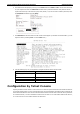
Moxa Managed Ethernet Switch/Extender EDS Configurator GUI Starting EDS Configurator To start EDS Configurator, locate and run the executable file edscfgui.exe. There are two ways to do this: • If the file was placed on the Windows desktop, it should appear as shown below. Simply double click the icon to run the program. • NOTE The Moxa EtherDevice Server Configurator window will open, as shown below. You may download the EDS Configurator software free of charge from Moxa’s website at www.moxa.com.
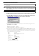
Moxa Managed Ethernet Switch/Extender EDS Configurator GUI 2. Once the search is complete, the Configurator window will display a list of all switches that were located. Search by IP Address Use the Search by IP Address utility to search for Moxa switches one at a time. Note that the search is conducted by IP address, so you should be able to locate any Moxa switch that is properly connected to your LAN, WAN, or the Internet. 1.
Moxa Managed Ethernet Switch/Extender EDS Configurator GUI 3. Click the Upgrade Firmware toolbar icon , or select Upgrade under the Firmware menu. If the switch is Locked, you will be prompted to input the switch’s User Name and Password. 4. Use the Open window to navigate to the folder that contains the firmware upgrade file, and then click the correct “*.rom” file (eds.rom in the example shown below) to select the file. Click Open to activate the upgrade process.
Moxa Managed Ethernet Switch/Extender EDS Configurator GUI 2. Click OK when the Export configuration to file OK message appears. 3. You may use a standard text editor, such as Notepad under Windows, to view and modify the newly created configuration file. Import Configuration The Import Configuration function is used to import an entire configuration from a text file to the Moxa switch.
Moxa Managed Ethernet Switch/Extender EDS Configurator GUI 3. The Setup Configuration window will be displayed, with a special note attached at the bottom. Parameters that have been changed will be indicated with a checkmark. You may make more changes if necessary, and then click OK to accept the changes. 4. Click Yes in response to the following warning message to accept the new settings.
Moxa Managed Ethernet Switch/Extender • EDS Configurator GUI Locked The switch is password protected, Broadcast Search was used to locate it, and the password has not yet been entered from within the current Configurator session. • Unlocked The switch is password protected, Broadcast Search was used to locate it, and the password was entered from within the current Configurator session.
A A. MIB Groups The Moxa switch/DSL extender comes with built-in SNMP (Simple Network Management Protocol) agent software that supports cold/warm start trap, line up/down trap, and RFC 1213 MIB-II. The standard MIB groups that the Moxa switch supports are as follows: MIB II.1—System Group sysORTable MIB II.2—Interfaces Group ifTable MIB II.4 – IP Group ipAddrTable ipNetToMediaTable IpGroup IpBasicStatsGroup IpStatsGroup MIB II.5—ICMP Group IcmpGroup IcmpInputStatus IcmpOutputStats MIB II.
Moxa Managed Ethernet Switch/Extender MIB Groups dot1dTpHCPortTable dot1dTpPortOverflowTable pBridgeMIB dot1dExtBase dot1dPriority dot1dGarp qBridgeMIB dot1qBase dot1qTp dot1qFdbTable dot1qTpPortTable dot1qTpGroupTable dot1qForwardUnregisteredTable dot1qStatic dot1qStaticUnicastTable dot1qStaticMulticastTable dot1qVlan dot1qVlanCurrentTable dot1qVlanStaticTable dot1qPortVlanTable The Moxa switch also provides a private MIB file, located in the file Moxa-[switch’s model name]-MIB.
Moxa Managed Ethernet Switch/Extender MIB Groups IcmpInputStatus IcmpOutputStats MIB II.6—TCP Group tcpConnTable TcpGroup TcpStats MIB II.7—UDP Group udpTable UdpStats MIB II.10—Transmission Group dot3 dot3StatsTable MIB II.11—SNMP Group SnmpBasicGroup SnmpInputStats SnmpOutputStats The Moxa DSL Ethernet Extender also provides a private MIB file, located in the file Moxa-[ extender’s model name]-MIB.my on the Moxa extender utility CD-ROM.