Moxa EtherDevice Switch EDS-G205 Hardware Installation Guide Second Edition, April 2009 © 2009 Moxa Inc. All rights reserved. Reproduction without permission is prohibited. Fl.4, No.135, Lane 235, Pao-Chiao Rd. Shing Tien City, Taipei, Taiwan, R.O.C.
Overview The EDS-G205 series is equipped with 5 Gigabit Ethernet ports, making it an ideal and economical solution for demanding, high bandwidth Gigabit Ethernet applications. In addition, the built-in relay warning function alerts system administrators when power failures or port breaks occur. The EDS-G205 series includes 2 models: one with an operating temperature range of 0 to 60°C, and the other one with extended operating temperature range of -40 to 75°C.
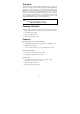
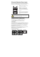
Panel Layout of EDS-G205 Front Panel View 1. Grounding screw 2 2. Terminal block for power input 3 4 5 (PWR1, PWR2) and relay output 3. Power input PWR1 LED 4. Power input PWR2 LED 5. Fault LED 6 7 6. TP port’s 10/10/1000 Mbps LED 8 7. Port number 8. 10/100/1000BaseT(X) Port 9. Model Name 10. DIP switches 9 11. Heat dissipation orifices 12. Screw hole for wall mounting kit Top Panel View 13.
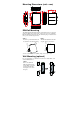
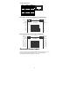
PWR1 PWR2 FAULT Mounting Dimensions (unit = mm) DIN-Rail Mounting The aluminum DIN-rail attachment plate should already be fixed to the back panel of the EDS when you take it out of the box. If you need to reattach the DIN-rail attachment plate, make sure the stiff metal spring is situated towards the top, as shown in the figures below. STEP 1: Insert the top of the DIN-rail into the slot just below the stiff metal spring. STEP 2: The DIN-rail attachment unit will snap into place as shown below.
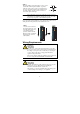
STEP 2: 6.0 mm Mounting the EDS on the wall requires 4 screws. Use the switch, with wall mount plates attached, as a guide to mark the correct locations of the 4 screws. The heads of the screws should be less than 6.0 mm in diameter, and 3.5 mm the shafts should be less than 3.5 mm in diameter, as shown in the figure at the right.
You should also pay attention to the following items: y Use separate paths to route wiring for power and devices. If power wiring and device wiring paths must cross, make sure the wires are perpendicular at the intersection point. NOTE: Do not run signal or communications wiring and power wiring in the same wire conduit. To avoid interference, wires with different signal characteristics should be routed separately.
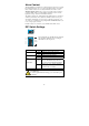
Wiring the Redundant Power Inputs The top two contacts and the bottom two contacts of the 6-contact terminal block connector on the EDS’s top panel are used for the EDS’s DC inputs. Top and front views of one of the terminal block connectors are shown here. STEP 1: Insert the negative/positive DC wires into the V-/V+ terminals. Top View STEP 2: To keep the DC wires from pulling loose, use a small flat-blade screwdriver to tighten the wire-clamp screws on the front of the terminal block connector.
1000BaseT RJ45 Pinouts Pin 1 2 3 4 5 6 7 8 MDI BI_DA+ BI_DABI_DB+ BI_DC+ BI_DCBI_DBBI_DD+ BI_DD- MDI-X BI_DB+ BI_DBBI_DA+ BI_DD+ BI_DDBI_DABI_DC+ BI_DC- 1 8 RJ45 (8-pin) to RJ45 (8-pin) Straight-Through Cable Wiring Straight-Through Cable Switch Port RJ45 Connector Tx+ TxRx+ RxDD+ DDDC+ DC- NIC Port RJ45 Plug Pin 1 RJ45 Connector Cable Wiring 3 6 1 2 4 5 7 8 3 6 1 2 4 5 7 8 Rx+ RxTx+ TxDC+ DCDD+ DD- RJ45 (8-pin) to RJ45 (8-pin) Cross-Over Cable Wiring Cross-Over Cable Switch Port (NIC Port) R
Alarm Contact The Moxa EtherDevice Switch has one Alarm Contact located on the top panel. For detailed instructions on how to connect the Alarm Contact power wires to the two middle contacts of the 6-contact terminal block connector, see the Wiring the Alarm Contact section on page 6. A typical scenario would be to connect the Fault circuit to a warning light located in the control room. The light can be set up to switch on when a fault is detected.
LED Indicators The front panel of the Moxa EtherDevice Switch contains several LED indicators. The function of each LED is described in the table below. LED Color PWR1 AMBER State On PWR2 FAULT Off Power is not being supplied to power input PWR1 On Power is being supplied to power input PWR2 Off Power is not being supplied to power input PWR2 On When the corresponding PORT alarm is enabled, and the port’s link is inactive.
Auto-Negotiation and Speed Sensing The EDS’s RJ45 Ethernet ports independently support auto-negotiation for transmission speeds of 10 Mbps, 100 Mbps, and 1000 Mbps, with operation according to the IEEE802.3 standard. This means that some nodes could be operating at 10 Mbps, while at the same time, other nodes are operating at 100 Mbps or 1000Mbps. Auto-negotiation takes place when an RJ45 cable connection is made, and then each time a LINK is enabled.
Regulatory Approvals Safety Hazardous Location EMI EMS Shock Free Fall Vibration WARRANTY UL508(Pending) UL/cUL Class I, Division 2, Groups A, B, C, and D; ATEX Class I, Zone 2, Ex nC nL IIC T4 (Pending) FCC Part 15, CISPR (EN55022) class A EN61000-4-2 (ESD), Level 3 EN61000-4-3 (RS), Level 3 EN61000-4-4 (EFT), Level 3 EN61000-4-5 (Surge), Level 3 EN61000-4-6 (CS), Level 3 EN61000-4-8 EN61000-4-11 EN61000-4-12 IEC60068-2-27 IEC60068-2-32 IEC60068-2-6 5 years Technical Support Contact Information www.