Moxa EtherDevice™ Switch EDS-510A Series Hardware Installation Guide Seventh Edition, July 2010 © 2010 Moxa Inc. All rights reserved. Reproduction without permission is prohibited. Fl.4, No.135, Lane 235, Pao-Chiao Rd. Shing Tien City, Taipei, Taiwan, R.O.C.
Package Checklist The EDS-510A is shipped with the following items. If any of these items are missing or damaged, please contact your customer service representative for assistance.
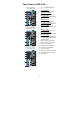
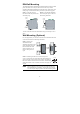
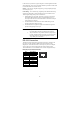
Panel Views of EDS-510A EDS-510A-3GT Front Panel View 5 4 3 MSTR/HEAD CPLR/TAIL 2 1. 2. 6 7 8 9 10 1 1 11 12 14 13 EDS-510A-1GT2SFP Front Panel View 5 4 3 MSTR/HEAD CPLR/TAIL 2 1 14 4. 6 7 8 9 10 1 3 2 MSTR/HEAD CPLR/TAIL 5. 11 12 6. PWR1: LED for power input 1 7. PWR2: LED for power input 2 13 8. FAULT: LED indicator 9. MSTR/HEAD: LED indicator EDS-510A-3SFP Front Panel View 5 4 3.
Top Panel: Top Panel View 1. Ground screw 2. RS-232 console port 5 3. 4. 6 5. Heat dissipation orifices DIP switches for Ring Master, Ring Coupler, and Turbo Ring 6-pin terminal block for DI 1, DI 2, and PWR 2 6-pin terminal block for PWR1, Relay 1, and Relay 2 1 V2- RS-232 CONSOLE PWR2 V2+ 2 DI1 I1 DI2 I2 3 RELAY1 1 4 2 3 4 OFF ------ RELAY2 MASTER COUPLER TURBO RING V1+ PWR1 V1- ON Rear Panel View 2 6. 1 7 Rear Panel: 8 7. Screw holes for Wall Mounting Kit 8.
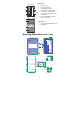
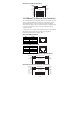
DIN-Rail Mounting The aluminum DIN-Rail attachment plate should already be fixed to the back panel of the EDS-510A when you take it out of the box. If you need to reattach the DIN-Rail attachment plate to the EDS-510A, make sure the stiff metal spring is situated towards the top, as shown by the following figures. STEP 1—Insert the top of the DIN-Rail into the slot just below the stiff metal spring. STEP 2—The DIN-Rail attachment unit will snap into place as shown in the following illustration.
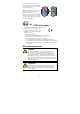
Do not screw the screws in all the way—leave about 2 mm to allow room for sliding the wall mount panel between the wall and the screws. STEP 3—Once the screws are fixed to the wall, insert the four screw heads through the wide parts of the keyhole-shaped apertures, and then slide the EDS-510A downwards, as indicated in the figure at the right. Tighten the four screws for more stability. II 3G MSTR/HEAD MSTR/HEAD CPLR/TAIL CPLR/TAIL ATEX Information 1. 2. 3. 4.
ATTENTION Safety First! Be sure to disconnect the power cord before installing and/or wiring your Moxa EtherDevice Switch. Calculate the maximum possible current in each power wire and common wire. Observe all electrical codes dictating the maximum current allowable for each wire size. If the current goes above the maximum ratings, the wiring could overheat, causing serious damage to your equipment. Please read and follow these guidelines: y Use separate paths to route wiring for power and devices.
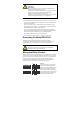
Wiring the Redundant Power Inputs The EDS-510A has two sets of power inputs—power input 1 and power input 2. The top two contacts and the bottom two contacts of the 6-pin terminal block connector on the EDS-510A’s top panel are used for the two digital inputs. The top and front views of one of the terminal block connectors are shown here. V2- V2+ V1- V1+ PWR2 PWR1 V2- V2+ V1- V1+ PWR2 PWR1 STEP 1: Insert the negative/positive DC wires into the V-/V+ terminals, respectively.
In this section, we present two types of diagrams—Pinout Diagrams and Cable Wiring Diagrams—that convey information about the ports and the cables used to connect the EDS-510A to other devices: Pinouts—The “Pinouts” diagrams display the type of signal passing through each of the port’s pins. Cable Wiring—The “Cable Wiring” diagrams present standard cable wiring schemes for cables used to connect the EDS-510A’s ports to other devices. These diagrams display three pieces of information: 1. 2. 3.
RJ45 (10-pin) to DB9 (F) Cable Wiring Moxa EtherDevice Server COM Port RJ45 Plug Pin 1 RJ45 Connector Female DB9 Connector Cable Wiring 1 DCD 2 DSR 3 RTS GND 4/7 5 TxD 6 RxD 8 CTS 9 DTR 1 6 7 5 3 2 8 4 DCD DTR CTS GND RxD TxD RTS DSR 10/100BaseT(X) Ethernet Port Connection The 10/100BaseT(X) ports located on the EDS-510A’s front panel are used to connect to Ethernet-enabled devices.
1000BaseT Ethernet Port Connection 1000BaseT data is transmitted on differential TRD+/- signal pairs over copper wires. MDI/MDI-X Port Pinouts Pin 1 2 3 4 5 6 7 8 Signal TRD(0)+ TRD(0)TRD(1)+ TRD(2)+ TRD(2)TRD(1)TRD(3)+ TRD(3)- 1 8 1000BaseSFP (mini-GBIC) Fiber Port The gigabit Ethernet ports on the EDS-510A-1GT2SFP and EDS-510A-3SFP are 1000BaseSFP Fiber ports, which require using the gigabit mini-GBIC fiber transceivers to work properly.
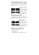
Turbo Ring DIP Switch Settings EDS-510A series are plug-and-play managed redundant Ethernet switches. The proprietary Turbo Ring protocol was developed by Moxa to provide better network reliability and faster recovery time. Moxa Turbo Ring’s recovery time is less than 300 ms (Turbo Ring) or 20 ms (Turbo Ring V2) —compared to a 3- to 5-minute recovery time for commercial switches—decreasing the possible loss caused by network failures in an industrial setting.
NOTE You must enable the Turbo Ring function first before using the DIP switch to activate the Master and Coupler functions. NOTE If you do not enable any of the EDS-510A switches to be the Ring Master, the Turbo Ring protocol will automatically choose the EDS-510A with the smallest MAC address range to be the Ring Master. If you accidentally enable more than one EDS-510A to be the Ring Master, these EDS-510A switches will auto-negotiate to determine which one will be the Ring Master.
10M (TP) 100M (TP) 1000M (TP/SFP) Off When the EDS-510A disables the coupling function, or is set as the Member of the Turbo Chain. On TP port’s 10 Mbps link is active. GREEN Blinking Data is being transmitted at 10 Mbps. Off TP port’s 10 Mbps link is inactive. On TP port’s 100 Mbps link is active. GREEN Blinking Data is being transmitted at 100 Mbps. Off TP port’s 100 Mbps link is inactive. On TP/SFP port’s 1000 Mbps link is active. GREEN Blinking Data is being transmitted at 1000 Mbps.
Optical Fiber—1000BaseSX/LX/LHX/ZX SX LX LHX ZX Wavelength 850 nm 1310 nm 1310 nm 1310 nm Max. Tx -4 dBm -3 dBm 1 dBm +5 dBm Min. Tx -9.5 dBm -9.5 dBm -4 dBm 0 dBm Rx Sensitivity -18 dBm -20 dBm -24 dBm -24 dBm Link Budget 8.5 dB 10.5 dB 20 dB 24 dB 550m (a) 275m (b) 1100m (c) 550m (d) 10km (e) 40km (e) 80km (f) 0 dBm -3 dBm -3 dBm -3 dBm Typical Distance Saturation a. [50/125 μm, 400 MHz*km] cable b. [62.5/125 μm, 200 MHz*km] cable c. [50/125 μm, 800 MHz*km] cable d.
Mechanical Casing IP30 protection, metal case Dimensions (W × H × D) 80.5 × 135 × 105 mm (3.17 × 5.31 × 4.13 in) Weight 1.17 kg Installation DIN-Rail, Wall Mounting Kit (optional) Environment Operating Temperature 0 to 60°C (32 to 140°F), standard models -40 to 75°C (-40 to 185°F), wide temp. models Storage Temperature -40 to 85°C (-40 to 185°F) Ambient Relative Humidity 5 to 95% (non-condensing) Regulatory Approvals Safety UL60950-1, UL 508, CSA C22.2 No.