Moxa EtherDevice Switch EDS-305-M12 Layer 2 M12/IP67 unmanaged Ethernet switches Hardware Installation Guide Fourth Edition, September 2009 © 2009 Moxa Inc. All rights reserved. Reproduction without permission is prohibited.
Overview The Moxa EtherDevice™ EDS-305-M12 series of 5-port smart Ethernet switches provides a hardened and cost-effective solution for your Ethernet connections. The EDS-305-M12 switches are IP67-rated to provide protection against shock and foreign particles. IP67-rated products have the following characteristics: (1) dust proof, (2) protection against the effects of temporary immersion in water.
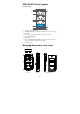
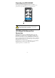
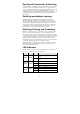
EDS-305-M12 Panel Layouts Front Panel View 1 2 7 3 5 4 6 8 7 1. 2. 3. 4. 5. 6. 7. 8. EDS-305-M12 8 7 M12 port’s 10/100 Mbps LED. 10/100BaseT(X) port (4-pin female shielded M12 socket with D coding). Port Label. Power input (5-pin male shielded M12 socket with A coding). Power input (PWR) LED. Model name. Holes for attaching the EDS-305-M12 to a wall with screws (there are 3 holes: bottom left, bottom right, and top middle). Grounding screws.
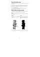
Panel/Wall Mounting To mount the EDS-305-M12 on the wall use the 3 screws included in the panel mounting kit. STEP 1: Make 3 screw holes on the wall based on the positions of the 3 screw holes on the switch shown in the mounting dimensions diagram. STEP 2: Insert one screw in the top-middle screw hole on the switch and screw it into the wall. STEP 3: Screw in the remaining 2 screws through the bottom-left and bottom-right holes on the switch.
Wiring Requirements WARNING Turn the power off before disconnecting modules or wires. The correct power supply voltage is listed on the product label. Check the voltage of your power source to make sure that you are using the correct voltage. Do NOT use a voltage greater than what is specified on the product label. These devices must be supplied by a SELV source as defined in the Low Voltage Directive 2006/95/EC and 2004/108/EC.
Grounding the EDS-305-M12 Grounding and wire routing help limit the effects of noise due to electromagnetic interference (EMI). Run the ground connection from the ground screw to the grounding surface prior to connecting devices. EDS-305-M12 ATTENTION This product is intended to be mounted to a well-grounded mounting surface such as a metal panel. 10/100BaseT(X) Ethernet Port Connection All EDS-305-M12 models have 5 10/100BaseT(X) Ethernet ports (4-pin shielded M12 socket with D coding).
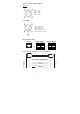
Pinouts for sockets on EDS-305-M12 TP Port TD + RD + TD RD - -Pin 1: -Pin 2: -Pin 3: -Pin 4: Power input -Pin 1: -Pin 2: -Pin 3: -Pin 4: -Pin 5: Input V+ Not assigned Input VNot assigned Function ground Pinouts for RJ45 (8-pin) RJ45 (8-Pin) 1 8 MDI Port Pinouts Pin 1 2 3 6 MDI-X Port Pinouts Signal Tx + Tx Rx + Rx - Pin 1 2 3 6 Signal Rx + Rx Tx + Tx - M12 (4-pin, M) to M12 (4-pin, M) Cross-Over Cable Wiring Cross-Over Cable Wiring Tx+ Rx+ TxRx- 1 2 3 4 1 2 3 4 -7- Tx+ Rx+ TxRx-
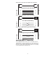
M12 (4-pin, M) to M12 (4-pin, M) Straight-Trough Cable Wiring Straight-through Cable Wiring Tx+ Rx+ TxRx- 1 2 3 4 1 2 3 4 Rx+ Tx+ RxTx- 1 2 3 6 Tx+ TxRx+ Rx- M12 (4-pin, M) to RJ45 (8-pin) Cross-Over Cable Wiring Cross-Over Cable Wiring Tx+ Rx+ TxRx- 1 2 3 4 M12 (4-pin, M) to RJ45 (8-pin) Straight-Trough Cable Wiring Straight-through Cable Wiring Tx+ Rx+ TxRx- 1 2 3 4 1 2 3 6 Rx+ RxTx+ Tx- Auto MDI/MDI-X Connection The Auto MDI/MDI-X function allows users to connect EDS-305-M12’s 10/100BaseTX
Dual Speed Functionality & Switching The EDS-305-M12’s 10/100 Mbps switched M12 ports auto negotiate with the connected device to use the fastest data transmission rate supported by both devices. All of Moxa’s EtherDevice switches are plug-and-play devices, so that software configuration is not required. The half/full duplex mode for the switched M12 ports is user dependent and changes (by auto-negotiation) to full or half duplex, depending on which transmission speed is supported by the attached device.
Auto-Negotiation and Speed Sensing All of the EDS-305-M12’s Ethernet ports independently support auto-negotiation for speeds in the 10BaseT and 100BaseTX modes, with operation according to the IEEE 802.3u standard. This means that some nodes could be operating at 10 Mbps, while at the same time, other nodes are operating at 100 Mbps. Auto-negotiation takes place when an M12 cable connection is made, and then each time a LINK is enabled.
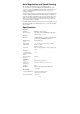
Operating relative humidity 5 to 95% (non-condensing) Regulatory Approvals Safety UL 508 Hazardous Location Rail Traffic Maritime UL/cUL Class1, Div.