
Network Card User Manual


EM-1240-LX User’s Manual Introduction
1-10
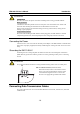
Connecting to the Network
Connect one end of the Ethernet cable to the EM-1240-LX’s 10/100M Ethernet port and the other
end of the cable to the Ethernet network. If the cable is properly connected, the EM-1240-LX will
indicate a valid connection to the Ethernet in the following ways:
y The top-right LED on the connector glows a solid green when connected to a 100 Mbps
Ethernet network.
y The top-left LED on the connector glows a solid orange when connected to a 10 Mbps
Ethernet network.
y The LEDs will flash when Ethernet packets are being transmitted or received.
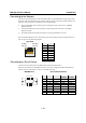
The 10/100 Mbps Ethernet LAN 1 and LAN 2 ports use 8-pin RJ45 connectors. Pinouts for these
ports are given in the following diagram.
8-pin RJ45
1
8
100 Mbps
indicator
10 Mbps
indicator
Pin Signal
1 ETx+
2 ETx-
3 ERx+
4 ---
5 ---
6 ERx-
7 ---
8 ---
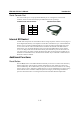
Connecting to a Serial Device
Connect the serial cable between the EM-1240-LX and the serial device(s).
Serial ports P1 and P2 use male DB9 connectors, and can be configured for RS-232/422/485 by
software. The pin assignments are shown in the following table:
DB9 Male Port
RS-232/422/485 Pinouts
12345
6789
Pin RS-232 RS-422
RS-485
(4-wire)
RS-485
(2-wire)
1 DCD TxDA(-) TxDA(-) ---
2 RxD TxDB(+) TxDB(+) ---
3 TxD RxDB(+) RxDB(+) DataB(+)
4 DTR RxDA(-) RxDA(-) DataA(-)
5 GND GND GND GND
6 DSR --- --- ---
7 RTS --- --- ---
8 CTS --- --- ---