EM-1240-LX User’s Manual www.moxa.com/product First Edition, November 2006 Moxa Systems Co., Ltd. Tel: +886-2-8919-1711 Fax: +886-2-8919-1722 Web: www.moxa.com Moxa Technical Support support@moxa.com Worldwide: support@usa.moxa.
EM-1240-LX User’s Manual The software described in this manual is furnished under a license agreement and may be used only in accordance with the terms of that agreement. Copyright Notice Copyright © 2006 Moxa Systems Co., Ltd. All rights reserved. Reproduction without permission is prohibited. Trademarks Moxa is a registered trademark of The Moxa Group. All other trademarks or registered marks in this manual belong to their respective manufacturers.
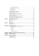
Table of Contents Chapter 1 Introduction ..................................................................................................1-1 Overview.................................................................................................................................. 1-2 Package Checklist .................................................................................................................... 1-2 Product Features .....................................................................
Enabling NAT at Bootup .............................................................................................. 4-7 Configuring Dial-in/Dial-out Service ...................................................................................... 4-8 Dial-out Service............................................................................................................ 4-8 Dial-in Service..............................................................................................................
1 Chapter 1 Introduction The Moxa EM-1240-LX Series of Mini RISC-based Ready-to-Run Embedded Computer features dual 10/100 Mbps Ethernet ports and four RS-232/422/485 serial ports in a built-in µClinux ARM9 module. In addition, EM-1240-LX provides SD memory card for storage expansion, offers high performance communication and unlimited storage in a super compact, palm-size module.
EM-1240-LX User’s Manual Introduction Overview The EM-1240-LX Series of mini RISC-based communication platforms are ideal for your embedded applications. The EM-1240-LX comes with 4 RS-232/422/485 serial ports and dual 10/100 Mbps Ethernet LAN ports to provide users with a versatile communication platform. The EM-1240-LX uses the MOXA ART ARM9 RISC CPU.
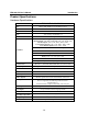
EM-1240-LX User’s Manual Introduction Product Specifications Hardware Specifications Model EM-1240 Embedded Module CPU MOXA ART ARM9 32-bit 192 MHz processor RAM 16 MB Flash 8 MB LAN Auto-sensing 10/100 Mbps x 2 LAN Protection Built-in 1.
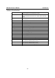
EM-1240-LX User’s Manual Introduction Software Specifications Kernel Protocol Stack File System Msh pppd PPPoE snmpd busybox Tinylogin Telnetd telnet inetd ftpd ftp boa ntpdate Linux Tool Chain Windows Tool Chain UC Finder µClinux Kernel 2.6.
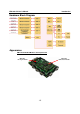
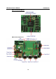
EM-1240-LX User’s Manual Introduction Hardware Block Diagram Appearance EM-1240 Embedded Module + Development Kit EM-1240 Development Kit EM-1240 Embedded Module 1-5
EM-1240-LX User’s Manual Introduction EM-1240 Embedded Module EM-1240 Development Kit 1-6
EM-1240-LX User’s Manual Introduction Dimensions EM-1240 Embedded Module.
EM-1240-LX User’s Manual Introduction Installing the EM-1240-LX If you would like to use the EM-1240 Embedded Module and the EM-1240 Development Kit, insert the EM-1240 Embedded Module vertically onto the Development Kit. Note that the pin marked “JP4” on the Embedded Module must be matched with the pin marked “JP6” on the Development Kit; and the Pin marked “JP3” on the Embedded Module must be matched with the Pin marked “JP4” on the Development Kit.
EM-1240-LX User’s Manual Introduction ATTENTION Safety First! Be sure to disconnect the power cord before installing and/or wiring your EM-1240-LX. Wiring Caution! Calculate the maximum possible current in each power wire and common wire. Observe all electrical codes dictating the maximum current allowable for each wire size. If the current goes above the maximum ratings, the wiring could overheat, causing serious damage to your equipment. Temperature Caution! Be careful when handling the EM-1240-LX.
EM-1240-LX User’s Manual Introduction Connecting to the Network Connect one end of the Ethernet cable to the EM-1240-LX’s 10/100M Ethernet port and the other end of the cable to the Ethernet network. If the cable is properly connected, the EM-1240-LX will indicate a valid connection to the Ethernet in the following ways: y y y The top-right LED on the connector glows a solid green when connected to a 100 Mbps Ethernet network.
EM-1240-LX User’s Manual Introduction Serial Console Port The serial console port is a 4-pin pin-header RS-232 port. It is designed for serial console terminals, which are useful for identifying the EM-1240-LX boot up message. Serial Console Port & Pinouts 4 3 2 1 Serial Console Cable Pin Signal 1 TxD 2 RxD 3 NC 4 GND Internal SD Socket The EM-1240-LX provides an internal SD socket for storage expansion. It allows users to plug in a Secure Digital (SD) memory card compliant with the SD 1.
EM-1240-LX User’s Manual Introduction ATTENTION Resetting to factory defaults will not format the user directory and erase all of the user’s data. Loading factory defaults will only load the configuration file. The files in the EM-1240-LX that will be replaced include: a. b. c. d. e. f. g. h. i. j. k. l. m. n. /etc/boa.conf /etc/hosts /etc/inittab /etc/password /etc/ramfs.img /etc/resolv.conf /etc/version /etc/group /etc/inetd.conf /etc/motd /etc/protocols /etc/rc /etc/services /home/httpd/index.
2 Chapter 2 Getting Started In this chapter, we explain the basic procedure for getting the EM-1240-LX connected and ready for your needs. In this chapter, we cover the following topics: Powering on the EM-1240-LX Connecting the EM-1240-LX to a PC ¾ Console Port ¾ Telnet Configuring the Ethernet Interface Installing a Secure Digital (SD) Memory Card Developing Your Applications ¾ Installing the EM-1240-LX Tool Chain ¾ Compiling Hello.
EM-1240-LX User’s Manual Getting Started Powering on the EM-1240-LX Connect the SG wire to the Shielded Contact located on the upper left corner of the EM-1240-LX, and then power on the EM-1240-LX by connecting the power adaptor. It takes about 16 seconds for the system to boot up. Once the system is ready, the Ready LED will light up. ATTENTION After connecting the EM-1240-LX to the power supply, it will take about 16 seconds for the operating system to boot up.
EM-1240-LX User’s Manual Getting Started Telnet If you know at least one of the two IP addresses and netmasks, then you can use Telnet to connect to the EM-1240-LX’s console. Default IP Address Default Netmask LAN 1 192.168.3.127 255.255.255.0 LAN 2 192.168.4.127 255.255.255.0 Telnet can be used locally by using a crossover Ethernet cable to connect your computer to the EM-1240-LX, or over a LAN or the Internet. The default IP addresses and netmasks are shown above.
EM-1240-LX User’s Manual Getting Started Configuring the Ethernet Interface In this section, we use the serial console to explain how to modify the EM-1240-LX’s network settings. 1. Change directories by issuing the command cd /etc. 2. Type the command vi rc to use the VI Editor to edit the configuration file. The IP addresses for the EM-1240-LX’s LAN1 and LAN2 are given as ifconfig eth0 192.168.3.127 ifconfig eth1 192.168.4.127 as shown in the following figure.
EM-1240-LX User’s Manual 3. Getting Started You may also configure the EM-1240-LX to request IP addresses from a DHCP server. In this case, use the sharp sign (#) to comment out one or both “ifconfig” lines, and then add the setting about the “dhcpcd” into the rc file as below. dhcpcd -p -a eth0 & dhcpcd -p -a eth1 & Note that the EM-1240-LX will send out DHCP broadcast packets, and then get the IP addresses from the first DHCP server that responds. 4.
EM-1240-LX User’s Manual Getting Started Installing a Secure Digital (SD) Memory Card The EM-1240-LX provides an internal SD socket for storage expansion. To access this socket, perform the following steps to install the SD memory card. Step 1: Find the exact location of the SD socket. Step 2: Insert the SD card into the socket. Make sure you insert with the right direction Step 3: Push the SD card inward.
EM-1240-LX User’s Manual Getting Started Developing Your Applications Step 1: Connect the EM-1240-LX to a Linux PC. Step 2: Install Tool Chain (GNU Cross Compiler & uClibc). Step 3: Configure cross compiler and uClibc environment variables. Step 4: Code & compile your program. Step 5: Download program to the EM-1240-LX via FTP or NFS. Step 6: Debug the program. If the program is OK, proceed to Step 7. If the program needs to be modified, go back to Step 4.
EM-1240-LX User’s Manual Getting Started Step 1: Double click the “tool-chain\windows\setup.exe” on the EM-1240-LX CD to begin the installation, then click [Next]. Step 2: Click [Browse…] to select your installation location. The default location is under C:\UC.
EM-1240-LX User’s Manual Getting Started Step 3: Click [Next] to select the local package files directory, and then click [Browse…] to select where your installation source is. The default path is the location of the “setup.exe” file. Step 4: Click [Next] to begin the package installation. You will see a progress bar that appears to check the MD5 status of each software package. Click [Next] to let the installer finish the installation.
EM-1240-LX User’s Manual Getting Started #make to compile Hello.c. Finally, execute the program to generate hello and hello.gdb. Uploading “Hello” to the EM-1240-LX To use FTP to upload hello to the EM-1240-LX, issue the following commands on the PC: #ftp 192.168.3.127 ftp> cd /home ftp> bin ftp> put ./hello ftp> quit #telnet 192.168.3.
EM-1240-LX User’s Manual Getting Started Running “Hello” on the EM-1240-LX To run the “Hello” program issue the following commands on the EM-1240-LX: # chmod 755 hello #./hello The words “hello world” are printed on the screen. ATTENTION Be sure to calculate the amount of Flash Memory used by the User File System in the Flash ROM.
EM-1240-LX User’s Manual Getting Started Make File Example Code The following Make File example codes are copied from the Hello example on the EM-1240-LX’s CD-ROM. srcdir = . LDFLAGS = -Wl,-elf2flt LIBS = CFLAGS = # Change these if necessary CC = arm-elf-gcc CPP = arm-elf-gcc -E all: hello hello: $(CC) -o $@ $(CFLAGS) $(LDFLAGS) $(LIBS) $@.c clean: rm -f $(OBJS) hello core *.
3 Chapter 3 Software Package This chapter includes information about the software that is used with EM-1240-LX Series products.
EM-1240-LX User’s Manual Software Package EM-1240-LX Software Architecture The pre-installed µClinux Operating System used by the EM-1240-LX follows the standard µClinux architecture, making programs that follow the POSIX standard easily ported to the EM-1240-LX by using the GNU Tool Chain provided by www.uClinux.org. In addition to the Standard POSIX API, device drivers for the buzzer, and UART for the serial ports are also included.
EM-1240-LX User’s Manual Software Package The partition sizes are hard coded into the kernel binary. You must rebuild the kernel to change the partition sizes. The flash memory map is shown in the following table.
EM-1240-LX User’s Manual Software Package EM-1240-LX Software Package bin upkernel passwd -> tinylogin login -> tinylogin tinylogin telnetd snmpd mail sh routed netstat arp chat pppd portmap ntpdate necid eraseall kversion init expand inetd hwclock ftpd ftp mke2fs e2fsck discard dhcpcd cpu busybox boa bf backupfs downramdisk upramdisk dev mtdblock1 mtdr1 mtd1 mtdblock0 mtdr0 mtd0 cum1 cum0 ttyM1 ttyM0 urandom random zero ttypf ttype ttypd ttypc ttypb ttypa ttyp9 ttyp8 ttyp7 ttyp6 ttyp5 ttyp4 ttyp3 ttyp2
EM-1240-LX User’s Manual bin Software Package dev ptyp0 ppp pio rtc ram1 ram0 null kmem mem cua0 console tty 3-5
4 Chapter 4 Configuring the EM-1240-LX In this chapter, we describe how to configure the EM-1240-LX Series products.
EM-1240-LX User’s Manual Configuring EM-1240-LX Enabling and Disabling Daemons The following daemons are enabled when the EM-1240-LX boots up for the first time. y y y y y SNMP Agent daemon: Telnet Server / Client daemon: Internet Daemons: FTP Server / Client daemon: WWW Server daemon: snmpd telnetd inetd ftpd boa ATTENTION How to enable/disable telnet/ftp server a. b. Edit the file ‘/etc/inetd.
EM-1240-LX User’s Manual Configuring EM-1240-LX Adding a Web Page Default Home Page address: /home/httpd/index.html You may change the default home page directory by editing the web server’s configuration file, located at: /etc/boa.conf Type the following command to edit the boa.conf file: /etc>vi boa.
EM-1240-LX User’s Manual Configuring EM-1240-LX Destination NAT (DNAT)—changes the first destination packet IP address MASQUERADE—a special form for SNAT. If one host can connect to the Internet, then other computers that connect to this host can connect to the Internet when the computer does not have an actual IP address. REDIRECT—a special form of DNAT that re-sends packets to a local host independent of the destination IP address. C.
EM-1240-LX User’s Manual Configuring EM-1240-LX The EM-1240-LX supports the following sub-modules. Be sure to use the module that matches your application.
EM-1240-LX User’s Manual Configuring EM-1240-LX Define policy for chain rules Usage: # iptables [-t tables] [-P] [INPUT, OUTPUT, FORWARD, PREROUTING, OUTPUT, POSTROUTING] [ACCEPT, DROP] -P: INPUT: OUTPUT: FORWARD: PREROUTING: POSTROUTING: Set the policy for the chain to the given target. For packets coming into the EM-1240-LX. For locally-generated packets. For packets routed out through the EM-1240-LX. To alter packets as soon as they come in. To alter packets as they are about to be sent out.
EM-1240-LX User’s Manual Configuring EM-1240-LX NAT NAT (Network Address Translation) protocol translates IP addresses used on one network into different IP addresses used on another network. One network is designated the inside network and the other is the outside network. Typically, the EM-1240-LX connects several devices on a network and maps local inside network addresses to one or more global outside IP addresses, and remaps the global IP addresses on incoming packets back into local IP addresses.
EM-1240-LX User’s Manual Configuring EM-1240-LX Configuring Dial-in/Dial-out Service Dial-out Service Direct cable connection: y Without username and password, use: />pppd connect ‘chat –v’ /dev/ttyM0 38400 crtscts& y With username and password, use: />pppd connect ‘chat –v’ user xxxxx password xxxxx /dev/ttyM0 38400 crtscts& Connect Using a Modem: y Use: />pppd connect ‘chat –v ATDT CONNECT’ user xxxxx password xxxxx /dev/ttyM0 38400 crtscts& ATTENTION If dial out fails, the pppd conn
EM-1240-LX User’s Manual Configuring EM-1240-LX : Password for user account To check if PPPOE is successfully connected, use the command: y />ifconfig ppp0 How to Mount a Remote NFS Server Currently, the EM-1240-LX only supports NFS (Network File System) clients. Users can open NFS service on a Linux PC to enable the EM-1240-LX to push data to it. The EM-1240-LX can use NFS to mount a remote disk as a local disk for data or log purposes. 1.
EM-1240-LX User’s Manual Configuring EM-1240-LX Upgrading the Kernel The EM-1240-LX kernel is em1240-1.x..bin, which can be downloaded from www.moxa.com. You must first download this file to your PC, and then use Console Terminal or Telnet Console to copy the file to the EM-1240-LX. You can save this file to the EM-1240-LX’s RAM disk, and then upgrade the kernel. The following is a step-by-step example.
EM-1240-LX User’s Manual Configuring EM-1240-LX Upgrading the Root File System & User Directory The EM-1240-LX uses JFFS2 for root file system and user directory. By default, the root file system is pre-set to READ only. The EM-1240-LX provides a read/write user’s directory in the JFFS2 file system. By using this user’s directory, the system configuration file and user’s program can be stored on this disk. Search the EM-1240-LX’s CD-ROM for the latest user directory file, or download the file from www.
EM-1240-LX User’s Manual Configuring EM-1240-LX User Directory Backup—EM-1240-LX to PC To enable the RAM disk, use the following command: />upramdisk />cd ramdisk Use the backupfs command to backup the file system. /ramdisk>backupfs /ramdisk/usrdisk-backup The file system will be backed up. Use ftp commands to transfer the usrdisk-backup to the FTP server on the PC.
EM-1240-LX User’s Manual Configuring EM-1240-LX |+bin Loading Factory Defaults The easiest way to “Load Factory Defaults” is with the “Upgrade User directory” operation. Refer to the previous section “How to Upgrade User Directory” for an introduction. You may also press the RESET button for more than 5 seconds to load the factory default configuration or input the command “ldfactory” in telnet console to restore the factory defaults.
EM-1240-LX User’s Manual Configuring EM-1240-LX To check the root file system (firmware) version of the EM-1240-LX, type: />fsversion You may also check the user directory version of the EM-1240-LX by using the following command: />cat /etc/version 4-14
5 Chapter 5 EM-1240-LX Device API In this chapter, we discuss the Device API for the EM-1240-LX Series.
EM-1240-LX User’s Manual EM-1240-LX Device API RTC (Real-time Clock) The device node is located at /dev/rtc. The EM-1240-LX supports µClinux standard simple RTC control. You must include to use these functions. 1. Function: RTC_RD_TIME int ioctl(fd, RTC_RD_TIME, struct rtc_time *time); Description: Reads time information from RTC. 2. Function: RTC_SET_TIME int ioctl(fd, RTC_SET_TIME, struct rtc_time *time); Description: Sets RTC time. Buzzer The device node is located at /dev/console.
6 Chapter 6 UC Finder The EM-1240-LX comes with a UC Finder utility, which has the sole purpose of searching the LAN or intranet for the EM-1240-LX units. For most of the applications, it is not easy to remember the IP addresses of Universal Communicators connected to the LAN. This is especially true for some problem solving and testing in the field. The UC Finder utility broadcasts messages over the LAN to search for IP addresses of Universal Communicators connected to the LAN.
EM-1240-LX User’s Manual UC Finder Windows UC Finder The following steps describe how to install UC Finder on a Windows PC. 1. Double click the UC Finder installation program, Setup.exe, to start the installation. 2. When the Welcome to the UC Finder Setup Wizard window opens, click Next to continue. 3. Select the Create a desktop icon option, and then click Next to continue.
EM-1240-LX User’s Manual UC Finder 4. Select the Launch UC Finder option, to use UC Finder immediately after the installation has finished, and then click Next to complete the installation. 5. When the UC Finder window opens, click Broadcast Search to search for all Universal Communicators connected to the LAN.
EM-1240-LX User’s Manual UC Finder 6. The Searching window will show the Universal Communicators that have been located. You can click Stop as soon as the Universal Communicator you are looking for is listed. 7. When the search is complete, the Broadcast Search window closes, and the Model, MAC Address, and IP Address of all Universal Communicators that were located will be listed in the UC Finder window.
EM-1240-LX User’s Manual UC Finder ATTENTION UC finder is designed solely to find IP addresses of networked Universal Communicators. It cannot be used to configure Universal Communicators over the network. If you need to configure UC’s IP address or other parameters, connect to UC’s console utility by Telnet (over the network) or serial console (using the serial console cable that came with the product).
A Appendix A System Commands busybox: µClinux normal command utility collection File manager cp ls ln mount rm chmod chown chgrp sync mv pwd df du mkdir rmdir head tail touch copy file list file make symbolic link file mount and check file system delete file change file owner & group & user change file owner change file group sync file system; save system file buffer to hardware move file display active file directly list active file system space estimate file space usage make new directory delete direc
EM-1240-LX User’s Manual System Commands Network ping route netstat ifconfig tracerout tftp telnet ftp iptables-restore iptables iptables-save ping to test network routing table manager display network status set network IP address trace route tftp protocol user interface to TELNET protocol file transfer protocol restore iptables configuration file to network iptables command save recent iptables configuration to file kill killall ps sleep kill process kill process by name report process status suspend
B Appendix B SNMP Agent with MIB II & RS-232 Like Group The EM-1240-LX has a built-in SNMP (Simple Network Management Protocol) agent that supports RFC1317 RS-232 like group and RFC 1213 MIB-II. The following table lists the variable implementation for the EM-1240-LX. The full SNMP object ID of the EM-1240-LX is “.iso.3.6.1.4.1.8691.12.7112” and “.iso.3.6.1.4.1.8691.12.1240”. Note: The EM-1240-LX does not support SNMP trap.
EM-1240-LX User’s Manual ip MIB ipForwarding ipDefaultTTL ipInReceives ipInHdrErrors ipInAddrErrors ipForwDatagrams ipInUnknownProtos ipInDiscards ipInDelivers ipOutRequests ipOutDiscards ipOutNoRoutes ipReasmTimeout ipReasmReqds ipReasmFails ipFragOKs ipFragFails ipFragCreates ipAddrTable ipAdEntAddr ipAdEntIfIndex ipAdEntNetMask ipAdEntBcastAddr ipAdEntReasmMaxSize ipRouteTable ipRouteDest ipRouteIfIndex ipRouteMetric1 ipRouteMetric2 ipRouteMetric3 ipRouteMetric4 ipRouteNextHop ipRouteType ipRouteProto ip
EM-1240-LX User’s Manual SNMP Agent with MIB II & RS-232 Like Group snmp MIB snmpInPkts snmpOutPkts snmpInBadVersions snmpInBadCommunityNames snmpInBadCommunityUses snmpInASNParseErrs snmpInTooBigs snmpInNoSuchNames snmpInBadValues snmpInReadOnlys snmpInGenErrs snmpInTotalReqVars snmpInTotalSetVars snmpInGetRequests snmpInGetNexts snmpInSetRequests snmpInGetResponses snmpInTraps snmpOutTooBigs snmpOutNoSuchNames snmpOutBadValues snmpOutGenErrs snmpOutGetRequests snmpOutGetNexts snmpOutSetRequests snmpOutT
C Appendix C EM-1240-LX FAQ FAQ 1 Why can I only use vfork( ),and am unable to use fork( )? Answer 1 uClinux only supports vfork( ). It does not support fork( ). Note that when using vfork( ), the parent process will hang until the child process calls an exec group API, or exits.
D Appendix D Service Information This appendix shows you how to contact Moxa for information about this and other products, and how to report problems. In this appendix, we cover the following topics.
EM-1240-LX User’s Manual Service Information Moxa Internet Services Customer satisfaction is our primary concern. To ensure that customers receive the full benefit of our products, Moxa Internet Services has been set up to provide technical support, driver updates, product information, and user’s manual updates. The following services are provided E-mail for technical support................................support@moxa.com.tw Website for product information: .............................http://www.moxa.
EM-1240-LX User’s Manual Service Information Problem Report Form Moxa EM-1240-LX Customer name: Company: Tel: Fax: Email: Date: 1. Moxa Product: EM-1240-LX 2. Serial Number: _________________ Problem Description: Please describe the symptoms of the problem as clearly as possible, including any error messages you see. A clearly written description of the problem will allow us to reproduce the symptoms, and expedite the repair of your product.
EM-1240-LX User’s Manual Service Information Product Return Procedure For product repair, exchange, or refund, the customer must: Provide evidence of original purchase. Obtain a Product Return Agreement (PRA) from the sales representative or dealer. Fill out the Problem Report Form (PRF). Include as much detail as possible for a shorter product repair time. Carefully pack the product in an anti-static package, and send it, pre-paid, to the dealer.