MOXA EtherDevice™ Switch EDS-518A Series User’s Manual www.moxa.com/product First Edition, April 2006 MOXA Networking Co., Ltd. Tel: +886-2-2910-1230 Fax: +886-2-2910-1231 Web: www.moxa.com MOXA Technical Support support@moxanet.tw Worldwide: support@moxa.
MOXA EtherDevice™ Switch EDS-518A Series User’s Manual The software described in this manual is furnished under a license agreement and may be used only in accordance with the terms of that agreement. Copyright Notice Copyright © 2006 MOXA Networking Co., Ltd. All rights reserved. Reproduction without permission is prohibited. Trademarks MOXA is a registered trademark of the MOXA Group. All other trademarks or registered marks in this manual belong to their respective manufacturers.
Table of Contents Chapter 1 Introduction ...............................................................................................1-1 Overview .............................................................................................................................. 1-2 Package Checklist................................................................................................................. 1-2 Features .......................................................................................
The Concept of Multicast Filtering ......................................................................... 3-40 Configuring IGMP Snooping .................................................................................. 3-43 Add Static Multicast MAC...................................................................................... 3-44 Configuring GMRP ................................................................................................. 3-45 GMRP Table .....................................
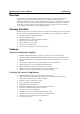
1 Chapter 1 Introduction Welcome to MOXA EtherDevice Switch EDS-518A Series, the Gigabit Managed Redundant Ethernet Switch designed specially for connecting Ethernet-enabled devices in industrial field applications.
EDS-518A Series User’s Manual Introduction Overview As the world’s network and information technology becomes more mature, the trend is to use Ethernet as the major communications interface in many industrial communications and automation applications. In fact, a whole new industry has sprung up to provide Ethernet products that comply with the requirements of demanding industrial applications.
EDS-518A Series User’s Manual Introduction Useful Utility and Remote Configuration y y Configurable using a Web browser, Telnet/Serial console, and Windows utility Send ping commands to identify network segment integrity Recommended Software and Accessories y y EDS-SNMP OPC Server Pro DR-4524, DR-75-24, DR-120-24 DIN-Rail 24 VDC Power Supply Series 1-3
2 Chapter 2 Getting Started This chapter explains how to access EDS-518A for the first time. There are three ways to access the switch: serial console, Telnet console, and web browser. The serial console connection method, which requires using a short serial cable to connect EDS-518A to a PC’s COM port, can be used if you do not know EDS-518A’s IP address. The Telnet console and web browser connection methods can be used to access EDS-518A over an Ethernet LAN, or over the Internet.
EDS-518A Series User’s Manual Getting Started RS-232 Console Configuration (115200, None, 8, 1, VT100) NOTE NOTE Connection Caution! 1. You cannot connect to EDS-518A simultaneously by serial console and Telnet. 2. You can connect to EDS-518A simultaneously by web browser and serial console, or by web browser and Telnet. However, we strongly suggest that you do NOT use more than one connection method at the same time.
EDS-518A Series User’s Manual Getting Started 3. The Communication Parameter page of the Property window opens. Select the appropriate COM port for Console Connection, 115200 for Baud Rate, 8 for Data Bits, None for Parity, and 1 for Stop Bits. 4. Click the Terminal tab, and select VT100 for Terminal Type. Click OK to continue. 5. Type 1 to select ansi/VT100 terminal type, and then press Enter.
EDS-518A Series User’s Manual Getting Started 6. The Console login screen will appear. Press Enter to open the Account pop-up selector and then select either admin or user. Use the keyboard’s down arrow to move the cursor to the Password field, enter the Console Password (this is the same as the Web Browser password; leave the Password field blank if a console password has not been set), and then press Enter. 7. EDS-518A’s Main Menu will be displayed.
EDS-518A Series User’s Manual Getting Started Configuration using a Telnet Console You may use Telnet to access EDS-518A’s console utility over a network. To be able to access EDS’s functions over the network (by Telnet or Web Browser) from a PC host that is connected to the same LAN as EDS-518A, you need to make sure that the PC host and EDS-518A are on the same logical subnet. To do this, check your PC host’s IP address and subnet mask. By default, EDS-518A’s IP address is 192.168.127.
EDS-518A Series User’s Manual NOTE Getting Started 3. The Console login screen will appear. Press Enter to open the Account pop-up selector and then select either admin or user. Use the keyboard’s down arrow to move the cursor to the Password field, enter the Console Password (this is the same as the Web Browser password; leave the Password field blank if a console password has not been set), and then press Enter. 4.
EDS-518A Series User’s Manual Getting Started NOTE Before accessing EDS-518A’s web browser interface, first connect one of its RJ45 Ethernet ports to your Ethernet LAN, or directly to your PC’s Ethernet NIC. You can establish a connection with either a straight-through or cross-over Ethernet cable. NOTE MOXA EDS-518A’s default IP is 192.168.127.253. Perform the following steps to access EDS-518A’s web browser interface. NOTE 1.
EDS-518A Series User’s Manual Getting Started Disabling Telnet and Browser Access If you are connecting EDS-518A to a public network, but do not intend to use its management functions over the network, we suggest disabling both Telnet Console and Web Configuration from the RS-232 Console’s Basic Settings Æ System Identification page, as shown in the following figure.
3 Chapter 3 Featured Functions This chapter explains how to access EDS-518A’s various configuration, monitoring, and administration functions. There are three ways to access these functions: RS-232 console, Telnet console, and web browser. The serial console connection method, which requires using a short serial cable to connect EDS-518A to a PC’s COM port, can be used if you do not know EDS-518A’s IP address.
EDS-518A Series User’s Manual Featured Functions Configuring Basic Settings The Basic Settings group includes the most commonly used settings required by administrators to maintain and control EDS-518A. System Identification The system identification items are displayed at the top of the web page, and will be included in alarm emails. Entering the system identification information makes it easier to identify the different switches connected to your network. Switch Name Setting Max.
EDS-518A Series User’s Manual Featured Functions Password EDS-518A provides two levels of access privileges: admin privilege gives read/write access to all EDS-518A configuration parameters, and user privilege provides read access only. You will be able to view the configuration, but will not be able to make modifications. ATTENTION EDS-518A’s default Password is not set (i.e., is blank).
EDS-518A Series User’s Manual Featured Functions Accessible IP MOXA EDS-518A uses an IP address-based filtering method to control access to EDS-518A units. Accessible IP Settings allows you to add or remove “Legal” remote host IP addresses to prevent unauthorized access. Access to EDS-518A is controlled by IP address. If a host’s IP address is in the accessible IP table, then the host will be allowed access to the EDS-518A.
EDS-518A Series User’s Manual Featured Functions Port Port settings are included to give the user control over Port Access, Port Transmission Speed, Flow Control, and Port Type (MDI or MDIX). An explanation of each configuration item follows: Enable Setting checked unchecked Description Allows data transmission through the port. Immediately shuts off port access.
EDS-518A Series User’s Manual Featured Functions Speed Setting Auto 100M-Full 100M-Half 10M-Full 10M-Half Description Factory Default Allows the port to use the IEEE 802.3u protocol to negotiate with connected devices. The port and connected devices will determine the best speed for that connection. Auto Choose one of these fixed speed options if the opposing Ethernet device has trouble auto-negotiating line speed.
EDS-518A Series User’s Manual Featured Functions Auto IP Configuration Setting Disable By DHCP By BOOTP Description Factory Default Set up EDS-518A’s IP address manually. EDS-518A’s IP address will be assigned automatically by the network’s DHCP server. Disable EDS-518A’s IP address will be assigned automatically by the network’s BOOTP server. Switch IP Address Setting IP Address of the EDS-518A Description Factory Default Identifies the EDS-518A on a TCP/IP network. 192.168.127.
EDS-518A Series User’s Manual Featured Functions Time EDS-518A has a time calibration function based on information from an NTP server or user specified Time and Date information. Functions such as Auto warning “Email” can add real-time information to the message. NOTE EDS-518A does not have a real time clock.
EDS-518A Series User’s Manual Featured Functions Time Server IP/Name Setting 1st Time Server IP/Name 2nd Time Server IP/Name Description IP or Domain address (e.g., 192.168.1.1 or time.stdtime.gov.tw or time.nist.gov). EDS-518A will try to locate the 2nd NTP Server if the 1st NTP Server fails to connect. Factory Default None Time Server Query Period Setting Query Period Description This parameter determines how frequently the time is updated from the NTP server.
EDS-518A Series User’s Manual Featured Functions Log Files Path and Name Setting Max. 40 Characters Description The path and file name of EDS-518A’s log file Factory Default None After setting up the desired path and file name, click Activate to save the setting, and then click Download to download the prepared file from the remote TFTP server, or click Upload to upload the desired file to the remote TFTP server.
EDS-518A Series User’s Manual Featured Functions Factory Default The Factory Default function is included to give users a quick way of restoring EDS-518A’s configuration settings to their factory default values. This function is available in the Console utility (serial or Telnet), and Web Browser interface. NOTE After activating the Factory Default function, you will need to use the default network settings to re-establish a web-browser or Telnet connection with your EDS-518A.
EDS-518A Series User’s Manual Featured Functions If all ports on both switch units are configured as 100BaseTX and they are operating in full duplex, the potential bandwidth of the connection will be up to 1.6 Gbps on the EDS-518A. This means that users can connect one EDS to another EDS by Port Trunking to double, triple, or quadruple the bandwidth of the connection.
EDS-518A Series User’s Manual Featured Functions Trunk Group (Maximum of 3 trunk groups) Setting Trk1, Trk2, Trk3 Description Display or designate the Trunk Type and Member Ports for Trunk Group 1, 2, 3. Factory Default Trk1 Description Designated MOXA proprietary trunking protocol Designated LACP (IEEE 802.
EDS-518A Series User’s Manual Featured Functions Configuring SNMP EDS-518A supports SNMP V1/V2c/V3. SNMP V1, and SNMP V2c use a community string match for authentication, which means that SNMP servers access all objects with read-only or read/write permissions using the community string public/private (default value). SNMP V3, which requires you to select an authentication level of MD5 or SHA, is the most secure protocol. You can also enable data encryption to enhance data security.
EDS-518A Series User’s Manual Featured Functions V1, V2c Write/Read Community Setting V1, V2c Read/Write Community Description Factory Default Uses a community string match with a maximum of 30 characters for authentication. The SNMP servers access private all objects with read/write permissions using the community string private. For SNMP V3, there are two levels of privileges for different accounts to access the EDS-518A. Admin privilege allows access, and authorization to read and write the MIB file.
EDS-518A Series User’s Manual Featured Functions User Data Encryption Key (for SNMP V1, V2c, V3 and V3 only) Setting Enable Disable Description Factory Default 8-character data encryption key is the minimum requirement for data encryption No (maximum of 30 characters) No data encryption No Trap Settings 1st Trap Server IP/Name Setting IP or Name Description Enter the IP address or name of the 1st Trap Server used by your network.
EDS-518A Series User’s Manual Featured Functions Turbo Ring and STP/RSTP cannot both be used on the network at the same time. The following table lists the key differences between each feature. Use this information to evaluate the benefits of each, and then determine which features are most suitable for your network. Topology Recovery Time Turbo Ring Ring < 300 ms STP Ring, Mesh Up to 30 sec.
EDS-518A Series User’s Manual Featured Functions Initial Setup 1. Select any two ports as redundant ports. 2. Connect the redundant ports to form the Turbo Ring You do not need to set the Master to use Turbo Ring. Master is only needed to identify which segment acts as the backup path. The actual topology of the redundant ring, i.e., which segment will be blocked, is determined by the number of EDS-518A switches that make up the ring, and where the “Ring Master” is located.
EDS-518A Series User’s Manual Featured Functions When the number of EDS-518A units in the Turbo Ring is odd. If there are 2N+1 EDS-518A units (an odd number) in the Turbo Ring, with EDS-518A units and segments labeled counterclockwise, then segment N+1 will serve as the backup path. Master For the example shown here, N=1, and therefore N+1=2.
EDS-518A Series User’s Manual Featured Functions Decide appropriate coupling ports in each switch and link them together. Next, assign one switch (e.g., Switch A) as coupler and set the proper coupling control port with another switch (e.g., Switch B) in the same Turbo Ring, and then connect them. The Coupler switch (e.g., Switch A) will monitor switch B through the coupling control port to decide if the coupling port’s backup path should be recovered or not.
EDS-518A Series User’s Manual Featured Functions Redundant Port Status This field indicates the current status of redundant ports. The state is “Forwarding” for normal transmission, “Blocked” for transmission that is stopped if this port is the backup path, and “Link down” for non-connection. Ring Coupling Indicates if the Ring Coupling function is “Enabled” or “Disabled.” Coupling Port Status This indicates the current status of coupling ports.
EDS-518A Series User’s Manual Featured Functions Rapid Spanning Tree Protocol (RSTP) implements the Spanning Tree Algorithm and Protocol defined by IEEE Std 802.1w-2001. RSTP provides the following benefits: y y The topology of a bridged network will be determined much more quickly compared to STP. RSTP is backward compatible with STP, making it relatively easy to deploy. For example: ¾ Defaults to sending 802.1D style BPDUs if packets with this format are received. ¾ STP (802.1D) and RSTP (802.
EDS-518A Series User’s Manual Featured Functions LAN 1 Bridge B Bridge A LAN 2 Bridge C LAN 3 What happens if a link failure is detected? As shown in next figure, the STP process reconfigures the network so that traffic from LAN segment 2 flows through Bridge B. LAN 1 Bridge B Bridge A LAN 2 Bridge C LAN 3 STP will determine which path between each bridged segment is most efficient, and then assigns a specific reference point on the network.
EDS-518A Series User’s Manual y Featured Functions Each port has a cost that specifies the efficiency of each link. The efficiency cost is usually determined by the bandwidth of the link, with less efficient links assigned a higher cost. The following table shows the default port costs for a switch: Port Speed 10 Mbps 100 Mbps 1000 Mbps Path Cost 802.1D, 1998 Edition 100 19 4 Path Cost 802.1w-2001 2,000,000 200,000 20,000 STP Calculation The first step of the STP process is to perform calculations.
EDS-518A Series User’s Manual Featured Functions STP Example The LAN shown in the following figure has three segments, with adjacent segments connected using two possible links. The various STP factors, such as Cost, Root Port, Designated Bridge Port, and Blocked Port are shown in the figure.
EDS-518A Series User’s Manual Featured Functions The following figure shows an example of a network that contains VLANs 1 and 2. The VLANs are connected using the 802.1Q-tagged link between Switch B and Switch C. By default, this link has a port cost of 100 and is automatically blocked because the other Switch-to-Switch connections have a port cost of 36 (18+18).
EDS-518A Series User’s Manual Featured Functions Now Active: This will show which communication protocol is being used—Turbo Ring, RSTP, or neither. Root/Not Root This field will appear only when selected to operate in RSTP mode. It indicates whether or not this EDS-518A is the Root of the Spanning Tree (the root is determined automatically). At the bottom of this page, the user can configure the “Settings” of this function.
EDS-518A Series User’s Manual Featured Functions Enable STP per Port Setting Enable/Disable NOTE Description Select to enable the port as a node on the Spanning Tree topology. Factory Default Disabled We suggest not enabling the Spanning Tree Protocol once the port is connected to a device (PLC, RTU, etc.) as opposed to network equipment. The reason is that it will cause unnecessary negotiation.
EDS-518A Series User’s Manual Featured Functions Using Traffic Prioritization EDS-518A’s traffic prioritization capability provides Quality of Service (QoS) to your network by making data delivery more reliable. You can prioritize traffic on your network to ensure that high priority data is transmitted with minimum delay. Traffic can be controlled by a set of rules to obtain the required Quality of Service for your network.
EDS-518A Series User’s Manual IEEE 802.1p Priority Level 0 1 2 3 4 5 6 7 Featured Functions IEEE 802.1D Traffic Type Best Effort (default) Background Standard (spare) Excellent Effort (business critical) Controlled Load (streaming multimedia) Video (interactive media); less than 100 milliseconds of latency and jitter Voice (interactive voice); less than 10 milliseconds of latency and jitter Network Control Reserved traffic Even though the IEEE 802.
EDS-518A Series User’s Manual 2. Featured Functions As the 802.1p priority levels are fixed to the traffic queues, the packet will be placed in the appropriate priority queue, ready for transmission through the appropriate egress port. When the packet reaches the head of its queue and is about to be transmitted, the device determines whether or not the egress port is tagged for that VLAN. If it is, then the new 802.1p tag is used in the extended 802.1D header.
EDS-518A Series User’s Manual Featured Functions Queuing Mechanism Setting Weighted Fair Strict Description EDS-518A has 4 priority queues. In the weighted fair scheme, an 8, 4, 2, 1 weighting is applied to the four priorities. This approach prevents the lower priority frames from being starved of opportunity for transmission with only a slight delay to the higher priority frames.
EDS-518A Series User’s Manual Featured Functions CoS Mapping Setting Low/Normal/ Medium/High Description Set the mapping table of different CoS values to 4 different egress queues. Factory 0: Low 1: Low 2: Normal 3: Normal 4: Medium 5: Medium 6: High 7: High TOS/DiffServ Mapping Setting Low/Normal/ Medium/High Description Set the mapping table of different TOS values to 4 different egress queues.
EDS-518A Series User’s Manual Featured Functions Using Virtual LAN Setting up Virtual LANs (VLANs) on your EDS-518A increases the efficiency of your network by dividing the LAN into logical segments, as opposed to physical segments. In general, VLANs are easier to manage. The Virtual LAN (VLAN) Concept What is a VLAN? A VLAN is a group of devices that can be located anywhere on a network, but which communicate as if they are on the same physical segment.
EDS-518A Series User’s Manual y y Featured Functions VLANs provide extra security: Devices within each VLAN can only communicate with other devices on the same VLAN. If a device on VLAN Marketing needs to communicate with devices on VLAN Finance, the traffic must pass through a routing device or Layer 3 switch. VLANs help control traffic: With traditional networks, congestion can be caused by broadcast traffic that is directed to all network devices, regardless of whether or not they need it.
EDS-518A Series User’s Manual y y Featured Functions Access Port: The port connects to a single device that is not tagged. The user must define the default port PVID that determines to which VLAN the device belongs. Once the ingress packet of this Access Port egresses to another Trunk Port (the port needs all packets to carry tag information), EDS-518A will insert this PVID into this packet to help the next 802.1Q VLAN switch recognize it.
EDS-518A Series User’s Manual Featured Functions Port 6 connect a single untagged device and assigns it to VLAN 5; it should be configured as “Access Port” with PVID 5. y Port 7 connects a single untagged device and assigns it to VLAN 4; it should be configured as “Access Port” with PVID 4. After proper configuration: y y y y y Packets from device A will travel through “Trunk Port 3” with tagged VID 5.
EDS-518A Series User’s Manual Featured Functions Management VLAN ID Setting VLAN ID ranges from 1 to 4094 Description Set the management VLAN of this EDS-518A. Factory Default 1 Port Type Setting Access Trunk Description This port type is used to connect single devices without tags. Select “Trunk” port type to connect another 802.1Q VLAN aware switch or another LAN that combines tagged and/or untagged devices and/or other switches/hubs.
EDS-518A Series User’s Manual Featured Functions VLAN Mode Setting Description 802.1Q VLAN Set VLAN mode to 802.1Q VLAN Port-based VLAN Set VLAN mode to Port-based VLAN Factory Default 802.1Q VLAN Port Setting Enable/Disable Description Set port to specific VLAN Group. Factory Default Enable (all ports belong to VLAN1) VLAN Table In 802.
EDS-518A Series User’s Manual NOTE Featured Functions The physical network can have a maximum of 64 VLAN settings. Using Multicast Filtering Multicast filtering improves the performance of networks that carry multicast traffic. This section explains multicasts, multicast filtering, and how multicast filtering can be implemented on your EDS-518A. The Concept of Multicast Filtering What is an IP Multicast? A multicast is a packet sent by one host to multiple hosts.
EDS-518A Series User’s Manual Featured Functions Network without multicast filtering Group 1 Multicast Stream Group 2 Multicast Stream Serial ports Console IGMP Group2 LAN 1 IGMP Group1 2 3 4 5 6 7 8 9 10 11 12 13 14 15 16 IGMP Group2 IGMP Group1 All hosts receive the multicast traffic, even if they don’t need it.
EDS-518A Series User’s Manual Featured Functions Query Mode Query mode allows the EDS-518A to work as the Querier if it has the lowest IP address on the subnetwork to which it belongs. IGMP querying is enabled by default on the EDS-518A to help prevent interoperability issues with some multicast routers that may not follow the lowest IP address election method. Enable query mode to run multicast sessions on a network that does not contain IGMP routers (or queriers).
EDS-518A Series User’s Manual Featured Functions Enabling Multicast Filtering Use the serial console or Web interface to enable or disable IGMP Snooping and IGMP querying. If IGMP Snooping is not enabled, then IP multicast traffic is always forwarded, flooding the network. Configuring IGMP Snooping IGMP Snooping provides the ability to prune multicast traffic so that it travels only to those end destinations that require that traffic, thereby reducing the amount of traffic on the Ethernet LAN.
EDS-518A Series User’s Manual Featured Functions Static Multicast Router Port Setting Select/Deselect NOTE Description Select the option to select which ports will connect to the multicast routers. It’s active only when IGMP Snooping is enabled. Factory Default Disabled At least one switch must be designated the Querier or enable IGMP snooping and GMRP when enabling Turbo Ring and IGMP snooping simultaneously. IGMP Table EDS-518A displays the current active IGMP groups that were detected.
EDS-518A Series User’s Manual Featured Functions Join Port Setting Select/Deselect Description Factory Default Select the appropriate options to select the join ports for None this multicast group. Configuring GMRP GMRP is a MAC-based multicast management protocol, whereas IGMP is IP-based. GMRP provides a mechanism that allows bridges and end stations to register or un-register Group membership information dynamically.
EDS-518A Series User’s Manual Featured Functions Using Bandwidth Management In general, one host should not be allowed to occupy unlimited bandwidth, particularly when the device malfunctions. For example, so-called “broadcast storms” could be caused by an incorrectly configured topology, or a malfunctioning device.
EDS-518A Series User’s Manual Featured Functions Ingress Setting Ingress rate Description Factory Default Select the ingress rate for all packets from the following N/A options: not limited, 3%, 5%, 10%, 15%, 25%, 35%, 50%, 65%, 85% Using Port Access Control EDS-518A provides two kinds of Port-Based Access Controls. One is Static Port Lock and the other is IEEE 802.1X. Static Port Lock EDS-518A can also be configured to protect static MAC addresses for a specific port.
EDS-518A Series User’s Manual Featured Functions Message Exchange Authentication server (RADIUS) Client EAPOL-Start EAP-Request/Identity EAP-Response/Identity RADIUS Access-Request EAP-Request/OTP RADIUS Access-Challenge EAP-Response/OTP RADIUS Access-Request EAP-Success RADIUS Access-Accept Port Authorized EAPOL-Logoff Port Unauthorized 1. 2. 3. 4. 5. 6.
EDS-518A Series User’s Manual 7. Featured Functions The authenticator sends “EAP Success” or “EAP Failure” based on the reply from the authentication server. Configuring Static Port Lock MOXA EDS-518A supports adding unicast groups manually if required. Setting MAC Address Port Description Add the static unicast MAC address into the address table. Fix the static address with a dedicated port. Factory Default None 1 Configuring IEEE 802.1X Database Option Setting Local (Max.
EDS-518A Series User’s Manual Featured Functions Radius Server Setting IP address or domain name Description The IP address or domain name of the RADIUS server Factory Default localhost Description The UDP port of the RADIUS Server Factory Default 1812 Server Port Setting Numerical Shared Key Setting alphanumeric (Max. 40 characters) Description Factory Default A key to be shared between the external RADIUS server None and EDS-518A. Both ends must be configured to use the same key.
EDS-518A Series User’s Manual Featured Functions 802.1X Re-Authentication EDS-518A can force connected devices to be re-authorized manually. 802.1X Re-Authentication Setting Enable/Disable Description Select the option to enable 802.1X Re-Authentication Factory Default Disable Local User Database Setup When setting the Local User Database as the authentication database, set the database first.
EDS-518A Series User’s Manual Featured Functions Local User Database Setup Setting User Name (Max. 30 characters) Password (Max. 16 characters) Description (Max. 30 characters) NOTE Description User Name for Local User Database Factory Default None Password for Local User Database None Description for Local User Database None The user name for the Local User Database is case-insensitive. Port Access Control Table The port status will indicate whether the access is authorized or unauthorized.
EDS-518A Series User’s Manual Featured Functions Configuring Email Warning The Auto Email Warning function uses e-mail to alert the user when certain user-configured events take place. Three basic steps are required to set up the Auto Warning function: 1. Configuring Email Event Types Select the desired Event types from the Console or Web Browser Event type page (a description of each event type is given later in the Email Alarm Events setting subsection). 2.
EDS-518A Series User’s Manual Featured Functions System Events Warning e-mail is sent when… Switch Cold Start Power is cut off and then reconnected. Switch Warm Start EDS-518A is rebooted, such as when network parameters are changed (IP address, subnet mask, etc.). EDS-518A is powered down. Power Transition (OnÆOff) Power Transition (OffÆOn) EDS-518A is powered up.
EDS-518A Series User’s Manual Featured Functions Email Setup Mail Server IP/Name Setting IP address Description The IP Address of your email server. Factory Default None Description Your email account name (typically your user name) Factory Default None Account Name Setting Max.
EDS-518A Series User’s Manual NOTE Featured Functions Auto warning e-mail messages will be sent through an authentication protected SMTP server that supports the CRAM-MD5, LOGIN, and PLAIN methods of SASL (Simple Authentication and Security Layer) authentication mechanism. We strongly recommend not entering your Account Name and Account Password if auto warning e-mail messages can be delivered without using an authentication mechanism.
EDS-518A Series User’s Manual System Events Featured Functions Warning Relay output is triggered when… Power Transition (OnÆOff) EDS-518A is powered on. Power Transition (OffÆOn) DI1 (OnÆOff) EDS-518A is powered down.
EDS-518A Series User’s Manual Featured Functions Configuring Line-Swap Fast Recovery Enable Line-Swap-Fast-Recovery Setting Enable/Disable Description Select this option to enable the Line-Swap-Fast-Recovery function Factory Default Enable Using Set Device IP To reduce the effort required to set up IP addresses, the EDS-518A series comes equipped with DHCP/BOOTP server and RARP protocol to set up IP addresses of Ethernet-enabled devices automatically.
EDS-518A Series User’s Manual Featured Functions • When using the Console utility, activate by first highlighting the Activate menu option, and then press Enter. You should receive the Set device IP settings are now active! (Press any key to continue) message. Configuring Set Device IP Desired IP Address Setting IP Address Description Set the desired IP of connected devices. Factory Default None Using Diagnosis MOXA EDS-518A provides two important tools for administrators to diagnose network systems.
EDS-518A Series User’s Manual Featured Functions STEP 1 Configure EDS-518A’s Mirror Port function from either the Console utility or Web Browser interface. You will need to configure three settings: Monitored Port Select the port number of the port whose network activity will be monitored. Mirror Port Select the port number of the port that will be used to monitor the activity of the monitored port.
EDS-518A Series User’s Manual Featured Functions graph displays data transmission activity by showing Packets/s (i.e., packets per second, or pps) versus sec. (seconds). In fact, three curves are displayed on the same graph: Unicast packets (in red color), Multicast packets (in green color), and Broadcast packets (in blue color). The graph is updated every few seconds, allowing the user to analyze data transmission activity in real-time.
EDS-518A Series User’s Manual Featured Functions Using the MAC Address Table This section explains the information provided by EDS-518A’s MAC address table. The MAC Address table can be configured to display the following EDS-518A MAC address groups.
EDS-518A Series User’s Manual Bootup Date Time System Startup Time Events NOTE Featured Functions This field shows how many times the EDS-518A has been rebooted or cold started. The date is updated based on how the current date is set in the “Basic Setting” page. The time is updated based on how the current time is set in the “Basic Setting” page. The system startup time related to this event. Events that have occurred. The following events will be record into EDS-518A’s Event Log table: 1.
EDS-518A Series User’s Manual 3. NOTE Featured Functions Select Yes to enter the EDS-518A’s web browser interface and access the web browser interface secured via HTTPS/SSL. MOXA provides a Root CA certificate .After installing this certificate into your PC or notebook, you can access the web browser interface directly and will not see any warning messages again. You may download the certificate from EDS-518A’s CD-ROM.
4 Chapter 4 EDS Configurator GUI EDS Configurator is a comprehensive Windows-based GUI that is used to configure and maintain multiple EDS-518A switches.
EDS-518A Series User’s Manual EDS Configurator GUI Starting EDS Configurator To start EDS Configurator, locate and then run the executable file edscfgui.exe. NOTE You may download the EDS Configurator software from MOXA’s website at www.moxa.com. For example, if the file was placed on the Windows desktop, it should appear as follows. Simply double click on the icon to run the program. The MOXA EtherDevice Server Configurator window will open, as shown below.
EDS-518A Series User’s Manual EDS Configurator GUI Once the search is complete, the Configurator window will display a list of all switches that were located. Search by IP address This utility is used to search for EDS-518A switches one at a time. Note that the search is conducted by IP address, so you should be able to locate any EDS-518A that is properly connected to your LAN, WAN, or even the Internet.
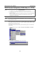
EDS-518A Series User’s Manual 3. 4. EDS Configurator GUI Click the Upgrade Firmware toolbar icon , or select Upgrade under the Firmware menu. If the switch is Locked, you will be prompted to input the switch’s User Name and Password. Use the Open window to navigate to the folder that contains the firmware upgrade file, and then click the correct “*.rom” file (eds.rom in the example shown below) to select the file. Click Open to activate the upgrade process.
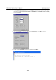
EDS-518A Series User’s Manual EDS Configurator GUI Export Configuration The Export Configuration utility is used to save the entire configuration of a particular EDS-518A to a text file. Take the following steps to export a configuration: 1. Highlight the switch (from the Server list in the Configurator window’s left pane), and then click the Export toolbar icon or select Export Configuration from the Configuration menu.
EDS-518A Series User’s Manual EDS Configurator GUI Import Configuration The Import Configuration function is used to import an entire configuration from a text file to EDS-518A. This utility can be used to transfer the configuration from one EDS-518A to another, by first using the Export Configuration function (described in the previous section) to save a switch configuration to a file, and then using the Import Configuration function. Perform the following steps to import a configuration: 1.
EDS-518A Series User’s Manual 4. EDS Configurator GUI Click Yes in response to the following warning message to accept the new settings. Unlock Server The Unlock Server function is used to open a password protected switch so that the user can modify its configuration, import/export a configuration, etc. There are six possible responses under the Status column.
EDS-518A Series User’s Manual EDS Configurator GUI 2. When the Unlock status window reports Progress as OK, click the Close button in the upper right corner of the window. 3. The status of the switch will now read either Unlocked or Unlocked Fixed.
A Appendix A MIB Groups MOXA EDS-518A comes with built-in SNMP (Simple Network Management Protocol) agent software that supports cold/warm start trap, line up/down trap, and RFC 1213 MIB-II. The standard MIB groups that MOXA EDS-518A series support are: MIB II.1 – System Group sysORTable MIB II.2 – Interfaces Group ifTable MIB II.4 – IP Group ipAddrTable ipNetToMediaTable IpGroup IpBasicStatsGroup IpStatsGroup MIB II.5 – ICMP Group IcmpGroup IcmpInputStatus IcmpOutputStats MIB II.
EDS-518A Series User’s Manual MIB Groups MIB II.10 – Transmission Group dot3 dot3StatsTable MIB II.11 – SNMP Group SnmpBasicGroup SnmpInputStats SnmpOutputStats MIB II.
EDS-518A Series User’s Manual MIB Groups EDS-518A also provides a private MIB file, located in the file “MOXA-EDS518A-MIB.my” on the EDS-518A Series utility CD-ROM. Public Traps: 1. Cold Start 2. Link Up 3. Link Down 4. Authentication Failure 5. dot1dBridge New Root 6. dot1dBridge Topology Changed Private Traps: 1. Configuration Changed 2. Power On 3. Power Off 4. Traffic Overloaded 5. Turbo Ring Topology Changed 6. Turbo Ring Coupling Port Changed 7.
B Appendix B Technology Standards Protocols MIB Interface RJ45 Ports Fiber Ports Console LED Indicators Alarm Contact Digital Input Optical Fiber 100BaseFX Distance: Multi mode: Single mode: Specifications IEEE802.3, 802.3u, 802.3x, 802.1D, 802.1w, 802.1Q, 802.1p IGMP V1/V2/V3 device, GVRP, SNMP V1/V2c/V3, DHCP Server/Client, BOOTP, TFTP, SNTP, SMTP, RARP and EDS-SNMP OPC server Pro (Optional) MIB-II, Ethernet-Like MIB, P-BRIDGE MIB, Q-BRIDGE MIB, Bridge MIB, RSTP MIB, RMON MIB Group 1,2.
EDS-518A Series User’s Manual Min. TX Output: Multi mode : Single mode: Max. TX Output: Multi mode : Single mode: Sensitivity: Multi mode : Single mode: Specifications -20 dBm 0 to 40 km, -5 dBm 0 to 80 km, -5 dBm -14 dBm 0 to 40 km, 0 dBm 0 to 80 km, 0 dBm -34 to -30 dBm -36 to -32 dBm 1000BaseSX/LX/LHX/ZX Distance: Multi mode: 0 to 500m, 850 nm (50/125 µm, 400 MHz*km) ‧ 1000BaseSX ‧ 1000BaseLX 0 to 275m, 850 nm (62.
EDS-518A Series User’s Manual Environmental Operating Temperature Storage Temperature Ambient Relative Humidity Regulatory Approvals Safety Hazardous Location EMI EMS Shock Freefall Vibration WARRANTY Specifications 0 to 60°C (32 to 140°F) -40 to 85°C (-40 to 185°F) 5% to 95% (non-condensing) UL60950, UL 508(Pending), CSA C22.2 No.
C Appendix C Service Information This appendix shows you how to contact MOXA for information about this and other products, and how to report problems. In this appendix, we cover the following topics.
EDS-518A Series User’s Manual Service Information MOXA Internet Services Customer satisfaction is our primary concern. To ensure that customers receive the full benefit of our products, MOXA Internet Services has been set up to provide technical support, driver updates, product information, and user’s manual updates. The following services are provided E-mail for technical support................................support@moxanet.com ...............................support@moxa.
EDS-518A Series User’s Manual Service Information Problem Report Form MOXA EDS-518A Series Customer name: Company: Tel: Fax: Email: Date: Serial Number: _________________ Problem Description: Please describe the symptoms of the problem as clearly as possible, including any error messages you see. A clearly written description of the problem will allow us to reproduce the symptoms, and expedite the repair of your product.
EDS-518A Series User’s Manual Service Information Product Return Procedure For product repair, exchange, or refund, the customer must: Provide evidence of original purchase. Obtain a Product Return Agreement (PRA) from the sales representative or dealer. Fill out the Problem Report Form (PRF). Include as much detail as possible for a shorter product repair time. Carefully pack the product in an anti-static package, and send it, pre-paid, to the dealer.