
Installation guide


Table Of Contents
- 10 -
2. The information to the left of the left vertical dashed lines gives the
pinouts of the relevant Moxa EtherDevice Switch port.
3. The information to the right of the right vertical dashed line gives the
pinouts of the opposing device’s port.
NOTE
1. The pin numbers for male DB9 and DB25 connectors, and
hole numbers for female DB9 and DB25 connectors are
labeled on the connector. However, the numbers are typically
quite small, so you may need to use a magnifying glass to see
the numbers clearly.
2. The pin numbers for both 8-pin and 10-pin RJ45 connectors
(and ports) are typically not labeled on the connector (or port).
Refer to the following Pinout and Cable Wiring diagrams to
see how RJ45 pins are numbered
RS-232 Connection
Moxa EDS-518A has one RS-232 (10-pin RJ45) console port, located on the
top panel. Use either an RJ45-to-DB9 or RJ45-to-DB25 cable (see the cable
following wiring diagrams) to connect Moxa EDS-518A’s console port to
your PC’s COM port. You may then use a console terminal program, such as
Moxa PComm Terminal Emulator, to access Moxa EDS-518A’s console
configuration utility.
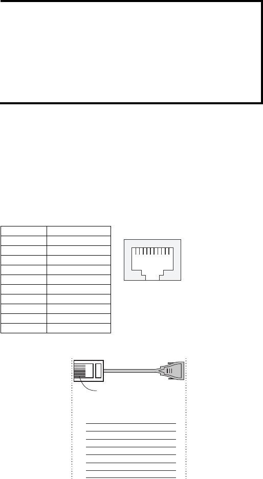
RJ45 (10-pin) Console Port Pinouts
Pin Description
1 ------
2 DSR
3 ------
4 GND
5 TxD
6 RxD
7 GND
8 ------
9 DTR
10 ------
110
RJ45 (10-pin) to DB9 (F) Cable Wiring
RJ45 Plug Pin 1
Moxa
EtherDevice
Server
RJ45
Connector
DCD
DSR
RTS
GND
TxD
RxD
CTS
DTR
COM Port
Female DB9
Connector
DCD
DTR
CTS
GND
RxD
TxD
RTS
DSR
Cable Wiring
1
2
3
4/7
5
6
8
9
1
6
7
5
3
2
8
4