
Computer Hardware User Manual


5-3
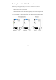
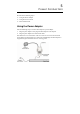
To use the 5 VDC Power over Serial option, enable jumpers JP2 and
JP3, as illustrated in the following diagram. Note that when using the
5 VDC option, power is
supplied via pins 9 and
10:
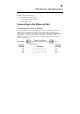
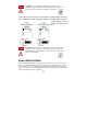
Power Status Check
Use the PWR LED indicator on NPort Express’s top panel to see if it is receiving
power. A red light indicates that power is being received. The absence of a light
indicates that power is not being received. If the unit is plugged in, or is receiving
power over cable, then an unlit PWR LED indicator shows that something is wrong
with the NPort Express unit’s operation.
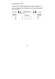
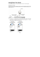
Do NOT force either jumper horizontally, as shown in the
diagram. Doing so could cause serious damage to your DE-211, or
to the serial device connected to DE-211’s serial port.
Do NOT force the jumper to connect the lower pin of JP2 to the
upper pin of JP3, as shown in the diagram. Doing so could cause
serious damage to your DE-211, or to the serial device connected
to DE-211’s serial port.