NPort Express Hardware Installation Guide for DE-211 Sixth Edition, May 2006 Moxa Technologies Co., Ltd. Tel: +886-2-8919-1230 Fax: +886-2-8919-1231 www.moxa.com support@moxa.com.tw (Worldwide) support@moxa.
NPort Express Hardware Installation Guide for DE-211 The software described in this manual is furnished under a license agreement and may be used only in accordance with the terms of that agreement. Copyright Notice Copyright © 2006 Moxa Technologies Co., Ltd. All rights reserved. Reproduction without permission is prohibited. Trademarks MOXA is a registered trademark of The Moxa Group. All other trademarks or registered marks in this manual belong to their respective manufacturers.
MOXA Internet Services Customer satisfaction is our number one concern. To ensure that customers receive the full benefit of our products, Moxa Internet Services has been set up to provide technical support, driver updates, product information, and user’s manual updates. The following services are provided: E-mail for technical support: address: or: support@moxa.com.tw support@moxa.com (Worldwide) (The Americas) Product information; latest drivers and documents: address: or http://www.moxa.
Table of Contents 1 A Introduction ................................................................................ 1-1 Features ....................................................................................... 1-2 Product Specifications.................................................................. 1-2 Package Checklist........................................................................ 1-4 Front/Top/Rear/Bottom Panel Views ............................................ 1-5 Overview ..........
1 1 Introduction Welcome to Moxa NPort Express, a compact palm-sized communications device that allows you to control RS-232/422/485 serial devices over a TCP/IP Ethernet. This chapter is an introduction to NPort Express and includes the following sections: ¾ Features ¾ Product Specifications ¾ Package Checklist ¾ Front/Top/Rear/Bottom Panel Views NPort Express DE-211 provides a data communications solution for connecting Windows and Linux hosts to asynchronous serial devices over a TCP/IP Ethernet.
Features ¾ ¾ ¾ ¾ ¾ ¾ ¾ ¾ 3-in-1 RS-232/422/485 interface and 10 Mbps Ethernet Supports 4- and 2-wire RS-485 with patented ADDC™ and built-in terminator Supports industrial 12/24 VDC power input and optional Power over Serial Terminal block accessory for easy RS-422/485 serial wiring Supports MAC based IP configuration Supports configuration store and copy for easy deployment Supports Windows Real COM driver and Linux real TTY driver Supports Driver Mode, TCP Server/Client, UDP Server/Client, Ethernet Modem
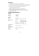
OS Supported Windows 95/98/ME/NT/2000/XP Real COM driver, Linux real tty driver Protocols TCP, IP, UDP, Telnet, RTelnet, DHCP, BootP, ICMP Operation Modes Driver Mode, TCP Server, TCP Client, UDP Server/Client, Ethernet Modem, Pair Connection Management Serial console Telnet console NPort Configurator for Windows/Linux Real COM Installer for Windows Monitor Utility for Windows Firmware upgrade function supported NPort Admin for Linux tty driver Power and Environment DC 12V to 30V Power requirements 150 mA (
Package Checklist DE-211/110V DE-211/230V 1 NPort Express DE-211 Universal Serial Device Server 1 NPort Express DE-211 Universal Serial Device Server Both models include y Windows 95/98/ME/NT/2000/XP Real COM driver, Linux real tty driver y NPort Management Suite software y Power Adapter y User’s Manual, software CD-ROM Optional Accessories NP21101 NP21102 NP21103 DIN Rail mounting kit 30 cm DB25 male to DB9 female RS-232 cable 30 cm DB25 male to DB9 male RS-232 cable DB25 terminal block kit for RS-422/4
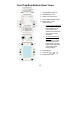
Front/Top/Rear/Bottom Panel Views 1. Female DB25 serial port 2. DIN Rail screw holes 3. Wall mount screw holes 4. RJ45 10BaseT Ethernet port 5. Reset button—press continuously for a. 3 sec to erase password After 3 sec, the ready LED will flash on/off every half second. Release the reset button at this time to erase password. b. 10 sec to load factory defaults After 10 sec, the ready LED will flash on/off every fifth of a second. Release the reset button at this time to load factory defaults. 6.
2 2 Overview This chapter includes: ¾ LED Indicators ¾ Housing • DIN Rail • Wall Mount LED Indicators NPort Express’s top panel contains five LED indicators, as described in the following table. LED Name PWR Link Ready LED Color red off orange off green blinking LED Function Power is on. Power is off, or power error condition exists. 10 Mbps Ethernet connection. Ethernet cable is disconnected, or has a short. NPort Server system is ready.
Housing DIN Rail For many industrial applications, you will find it convenient to use the DIN Rail attachments, as shown below. STEP 1: Use 2 screws per ear to attach DIN Rail mounts to each of NPort Express’s two ears. ⇒ STEP 2: Insert the top of the DIN Rail into slot A of the DIN Rail mount. STEP 3: Push the bottom of NPort Express so that the bottom of the DIN Rail snaps into slot B of the DIN Rail mount. NOTE: The Din Rail mounting kit is an optional accessory.
Wall Mount For many industrial applications, you will find it convenient to mount NPort Express on the wall, using two screws, as indicated below. STEP 1: Screw two screws, separated by 7.8 cm, into the wall. The heads of the screws should be no greater than 6.5 mm in diameter, and the shafts should be no greater than 3 mm in diameter. Do not screw the screws in all the way—leave a space of about 2 mm to allow room for sliding the NPort Express unit’s ears between the wall and the screws.
3 3 Serial Installation We discuss the following topics: ¾ DIP Switch Settings ¾ DB25 Female Connector Pinout ¾ RS-232 Wiring ¾ RS-422 Wiring ¾ 4-Wire RS-485 Wiring • Using a DB25 connector • Using the optional Terminal Block ¾ Enabling a Termination Resistor • Enabling the Built-In 120 Ω Terminator • Enabling a User-Supplied Terminator DIP Switch Settings The top panel of NPort Express contains the following table, which describes how to set up the serial port using the four DIP switches loc
Switch SW1 controls the function of the serial port (ON, or up, for RS-232 Console connection, and down for Data Communication, such as when NPort Express is connected to your serial device). Note that after changing the setting of SW1, NPort Express will reboot to initialize the new setting. You must wait a few seconds for the green Ready light to blink off and then on again, indicating that the function of the serial port has been changed.
RS-232 Wiring * NP21101 is an optional accessory for DE-211 * NP21102 is an optional accessory for DE-211 3-3
NOTE: The following pinout diagram shows how to use a DB25 (M) to DB25 (F) cable. NOTE: In Ethernet Modem Mode, you need a special cable—shown in the following pinout diagram—to simulate a DCD signal.
RS-422 Wiring Using a DB25 Connector Using the Optional Terminal Block NOTE: Use a flathead screwdriver to tighten the two attachment screws that connect the terminal block to NPort Express.
RS-485 Wiring Using a DB25 Connector 3-6
Using the Optional Terminal Block 4-wire RS-485 Terminal Block Wiring NOTE: Use a flathead screwdriver to tighten the two attachment screws that connect the terminal block to NPort Express. 2-wire RS-485 Terminal Block Wiring NOTE: Use a flathead screwdriver to tighten the two attachment screws that connect the terminal block to NPort Express.
NOTE: When setting up a multidrop network, a daisy-chained network should be used. Construct your device-to-device wiring as indicated in the above figure. Enabling a Termination Resistor For RS-422/485 serial communications, when an electrical signal travels through two different resistance junctions in a transmission line, the impedance mismatch will sometimes cause signal reflection. Signal reflection causes signal distortion, which in turn will contribute to communication errors.
Enabling the Built-In 120 Ω Terminator To enable NPort Express’s built-in 120 Ω termination resistor, you must short the bottom two pins of jumper 6 (JP6), on DE-211’s circuit board. To do this: 1. Use a screwdriver to remove DE-211’s outer protective case, and then locate JP6, as shown in the figures below. 2. By default, the top two pins of JP6 are shorted, which means that the built-in 120 Ω termination resistor is disabled (completely removing the jumper from the pins also disables the resistor). 3.
Enabling a User-Supplied Terminator When using the terminal block, you may install your own external terminator resistor by connecting the ends of the resistor directly to inputs 2 and 3, or by connecting the two ends of the resistor to the wires that emanate from inputs 2 and 3, as shown in the following diagrams.
4 4 Ethernet Installation We discuss the following topics: ¾ Connecting to the Ethernet Port • Connecting to a Hub or Switch • Connecting to a PC Connecting to the Ethernet Port Connecting to a Hub or Switch For most applications, you will simply plug one end of your Ethernet cable into NPort Express’s 10BaseT port, and the other end into a Hub or Switch that is connected to your network.
Connecting to a PC In some cases, such as when configuring drivers and software, you will find it convenient to hook NPort Express directly to your computer’s Ethernet card. To do this, you will need to use a cross-over Ethernet cable. This type of Ethernet cable is harder to find, although you can make your own cable by referring to the following cable wiring diagram.
5 5 Power Connection We discuss the following topics: ¾ Using the Power Adapter ¾ Using Power Over Serial ¾ Power Status Check Using the Power Adapter Take the following steps to connect NPort Express’s power adapter. 1. Plug the power adapter’s DC plug into NPort Express’s DC-IN jack. 2. Plug the power adapter into an electrical outlet. Note that there is no on/off switch. The server turns on as soon as the connected power adapter is plugged into a live outlet.
Using Power Over Serial Take the following steps to set up NPort Express’s Power over Serial option. IMPORTANT NOTICE You may not use the power adapter and Power Over Serial option at the same time. Using both power options at the same time could cause irreparable damage to your NPort Express unit. (1) To use the 12 – 30 VDC Power over Serial option, enable jumpers JP4 and JP5, as illustrated in the following diagram.
Do NOT force either jumper horizontally, as shown in the diagram. Doing so could cause serious damage to your DE-211, or to the serial device connected to DE-211’s serial port. To use the 5 VDC Power over Serial option, enable jumpers JP2 and JP3, as illustrated in the following diagram. Note that when using the 5 VDC option, power is supplied via pins 9 and 10: Do NOT force the jumper to connect the lower pin of JP2 to the upper pin of JP3, as shown in the diagram.
A A Declaration of Conformity Manufacturer’s Name: Moxa Technologies Co., Ltd. Manufacturer’s Address: Fl.4, No.135, Lane 235, Pao-Chiao Rd., Shing Tien City, Taipei, Taiwan, R.O.C.
B B Problem Report Form NPort Express Customer name: Company: Tel: Fax: Email: Date: 1. 2. 3. 4. 5. 6. 7. 8. 9. 10.
C C Return Procedure For product repair, exchange, or refund, the customer must: ♦ Provide evidence of original purchase. ♦ Obtain a Product Return Agreement (PRA) from the sales representative or dealer. ♦ Fill out the Problem Report Form (PRF). Include as much detail as possible for a shorter product repair time. ♦ Carefully pack the product in an anti-static package, and send it, pre-paid, to the dealer.