NPort 6110 Modbus/TCP to Serial Communication Gateway User’s Manual Second Edition, November 2004 Moxa Technologies Co., Ltd. Tel: Fax: Web: +886-2-8919-1230 +886-2-8919-1231 www.moxa.com MOXA Technical Support Worldwide: support@moxa.com.tw The Americas: support@moxa.
2 NPort 6110 Modbus/TCP to Serial Communication Gateway The software described in this manual is furnished under a license agreement and may be used only in accordance with the terms of that agreement. Copyright Notice Copyright 2004 Moxa Technologies Co., Ltd. All rights reserved. Reproduction without permission is prohibited. Trademarks MOXA is a registered trademark of The Moxa Group. All other trademarks or registered marks in this manual belong to their respective manufacturers.
MOXA Internet Services Customer satisfaction is our number one concern. To ensure that customers receive the full benefit of our products, Moxa Internet Services has been set up to provide technical support, driver updates, product information, and user’s manual updates. The following services are provided: E-mail for technical support Worldwide: The Americas: support@moxa.com.tw support@moxa.com World Wide Web (WWW) site for product information address: or http://www.moxa.com http://www.moxa.com.
Table of Contents 1. Introduction....................................................................................... 1-1 Overview....................................................................................... 1-1 Features........................................................................................ 1-2 Product Specifications .................................................................. 1-3 Package Checklist ........................................................................
Unlock ................................................................................. 4-15 Upgrade Firmware .............................................................. 4-15 Remote Monitoring and Management................................. 4-17 5. Troubleshooting ............................................................................... 5-1 6. Pin Assignments............................................................................... 6-1 A. Declaration of Conformity.............................
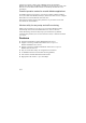
1 1. Introduction Welcome to Moxa NPort 6110 Modbus/TCP to Serial Communication Gateway, an easy-to-use Ethernet to RS-232/422/485 Modbus Gateway.
port that can connect to many types of Modbus device. By translating Modbus/TCP (Ethernet) and Modbus/ASCII/RTU (Serial) protocols, a PLC with Ethernet can use the RS-232/485 interface to seamlessly communicate with instruments. Powerful operation modes for versatile Modbus applications For Modbus protocol conversions, it is necessary to define a Master and Slave device, but unlike other Modbus Gateways, NPort 6110 allows users to configure Master/Slave for both the Ethernet and serial sides.
Product Specifications LAN Ethernet Protection Serial Interface RS-232 Signals RS-422 Signals RS-485 2-wire Signals Serial Line Protections RS-485 Data Direction 10/100 Mbps, RJ45 Built-in 1.
Environmental Operating Temperature Storage Temperature 0 to 55°C (32 to 131°F), 5 to 95% RH -20 to 85°C (-4 to 185°F), 95% RH Regulatory Approvals EMC FCC Class B, CE Class B Safety CUL, TÜV Package Checklist NPort 6110 Modbus/TCP to Serial Communication Gateway with 100-240 VAC power adaptor (US, Euro plugs included) All models include: ! NPort 6110 ! Software and documentation CD-ROM ! 100-240 VAC power adapter, US plug, 12V, 400 mA ! Euro plug included Optional Accessories: ! DK-35A DIN-Rail Mounti
Front/Top/Rear/Bottom Panel Views RESET 9-30V 10/100M Ethernet 6 (0.24") PWR 4 (0.16") Link 21.3 (0.8") 25 (0.98") 6110 Modbus/TCP to Serial Communication Gateway 12.5 (0.49") 100.4 (3.95") Ready 7 (0.28") RS-232/422/485 22.0 (0.87") 42.3 (1.67") unit = mm (inch) 67 (2.64") 78 (3.07") 90.2 (3.
2 2. Getting Started This chapter includes: ❑ Power Connection ❑ Serial Installation ❑ Ethernet Installation ❑ Software Installation ❑ Housing " DIN-Rail " Wall Mount Power Connection Take the following steps to connect NPort 6110’s power adapter. 1. Plug the power adapter’s DC plug into NPort 6110’s DC-IN jack. 2. Plug the power adapter into an electrical outlet. Note that there is no on/off switch.
Ethernet Installation There are two ways to use the 10/100BaseT Ethernet jack located on NPort 6110’s front panel: 1. For most applications using NPort 6110, you will simply plug one end of an Ethernet cable into NPort 6110’s 100BaseT jack, and plug the other end into an Ethernet hub/switch connected to your network. In this case, use a regular straight-through Ethernet cable. 2. When configuring NPort 6110, you may connect NPort 6110 directly to your computer’s Ethernet connector.
2. You will be greeted by the Welcome window. Click on Next to continue. 3. Enter your Name and Company name in the spaces provided, and then click on Next to continue. 4. When the Choose Destination Location window appears, click on Next to continue. If you would like to use a Destination Directory different than the one displayed, first click on Browse… to locate your folder of choice, and then click on Browse.
5. If desired, modify the highlighted name in the Program Folders text box (this is the name that will appear under Start # Programs) and then click on Next to continue.
6. Click on Next to start copying the software files. 7. Wait patiently while the files are being copied. The procedure should only take a few seconds. 8. The NPort Modbus Gateway Utility folder will open showing the Modbus Gateway Configurator icon.
9. You may also view this program shortcut by clicking on Start # Programs # NPort Modbus Gateway Utility # Modbus Gateway Configurator, as shown below.
Housing DIN-Rail For many industrial applications, you will find it convenient to use the DIN-Rail attachments, as shown below. STEP 1: Use 2 screws per ear to attach DIN-Rail mounts to each of NPort 6110’s two ears. ⇒ STEP 2: Insert the top of the DIN-Rail STEP 3: Push the bottom of NPort into the top slot of the 6110 so that the bottom of the DIN-Rail mount. DIN-Rail snaps into DIN-Rail mount’s bottom slot. NOTE: The DIN-Rail mounting kit is an optional accessory.
Wall Mount For many industrial applications, you will find it convenient to mount NPort 6110 on the wall, using two screws, as indicated below. STEP 1: Screw two screws, separated by 7.8 cm, into the wall. The heads of the screws should be no greater than 6.5 mm in diameter, and the shafts should be no greater than 3 mm in diameter. Do not screw the screws in all the way—leave a space of about 2 mm to allow room for sliding the NPort 6110 unit’s ears between the wall and the screws. 6.5 mm 7.
3 3. Typical Modbus Applications In this chapter, we introduce three typical Modbus applications. Serial master device talks to serial slave devices over the Internet Let traditional Modbus serial devices talk over the Internet… Many traditional serial Modbus devices can talk over RS-485, but the RS-485 network limits the maximum number of Modbus devices to 32, provided the transmission distance does not exceed 1.2 km.
Ethernet master devices talk to multiple serial slave devices Connect all Modbus devices over the Ethernet network… Most host computers and newly developed PLCs support the Ethernet interface and run Modbus/TCP. NPort 6110 Modbus Gateway is needed to link discrete Serial Modbus Devices for data collection and control. Each NPort 6110 supports Modbus/TCP over Ethernet, which allows up to 7 connections. The software configurable serial interface supports either RS-232 or RS-422/485.
Serial master devices talk to multiple Ethernet slave devices Link the Serial Master device with Ethernet Slave devices… Many HMI (Human Machine Interface) systems use a serial interface and are required to access a discrete DCS (Data Control System). These days however, more and more DCSs support Ethernet and run under Modbus/TCP slave mode. In this case, NPort 6110 Modbus Gateway is the ideal solution to link the HMI to distributed DCSs over an Ethernet network.
4 4.
Starting Modbus Gateway Configurator To start Modbus Gateway Configurator, click on Start # Programs # NPort Modbus Gateway Utility # Modbus Gateway Configurator. The Modbus Gateway Configurator window will open as shown below.
Searching for NPort 6110 There are two methods available to search the network for NPort 6110s. Broadcast Search is used to locate all NPort 6110s connected to the same LAN as the host, and Search by IP is used to locate a specific NPort 6110, particularly if it is located outside the LAN and can only be accessed by going through a router. Broadcast Search To use the Broadcast Search function, click on the Broadcast Search icon from the toolbar, or select Broadcast Search under the Locate Gateway menu.
When the Search by IP Address window opens, input the IP address of the NPort 6110 you want to search for, and then click OK. If the search is successful, information related to the NPort 6110 will be displayed in the Modbus Gateway Configurator window. NOTE If using the Search by IP Address function fails to locate the NPort 6110, one possible reason is that the IP address you entered to conduct the search is incorrect. Try retyping the IP address and then redo the search.
The Configuration window opens to the Network Settings page. Refer to the following subsections to learn more about how to configure NPort 6110’s various settings. Network Settings The Network Settings page is used to configure Modbus Gateway Name, IP Address, Netmask, Default Gateway, and IP Configuration. At the top of the page you may also view the Model Name, MAC Address, and Serial Number of the NPort 6110. These three parameters are set at the factory and cannot be modified by the user.
Network Settings Value Notes Choose a name that easily Modbus Gateway Name Alphanumeric identifies the Gateway’s location, function, etc. The IP (Internet Protocol) 32-bit number, default = IP Address address identifies the server on 192.168.127.254 the TCP/IP network. 32-bit number, Identifies the server as belonging default = Netmask to a Class A, B, or C network. 255.255.255.0 Setting Default Gateway IP Configuration IP address of the router that provides network access outside the server’s LAN. 1.
4-7
Modbus Settings Value Notes 1 Modbus RTU Slave Modbus ASCII Slave2 Set the Modbus type of the serial device attached to Attached Serial Device type Modbus RTU Master3 NPort 6110’s serial port. Modbus ASCII Master4 NPort Modbus Gateway provides this setting for 100 to 3276 ms; those PLCs that need a Initial delay time default = 100 ms longer time for their system to be initialized.
4. Modbus ASCII Master mode works the same as Modbus/RTU Master mode, except that the data format is Modbus/ASCII. 5. When the NPort Modbus Gateway receives a command from the serial port, the ID No. range table is used identify which IP address to connect to (e.g., if ID No. = 15, then according to the table in the Modbus Settings page shown above, the command is sent to the device that has IP of 192.168.127.3.
Setting Auto Slave Unit ID Character Timeout Message Timeout Modbus/TCP Exception Advanced Modbus Settings Value Notes Select Enable when Enable (Default) multiple Modbus devices are accessible at the same Disable IP address.1 This parameter is active 10 to 3000 ms when the attached serial (default = 100 ms) device is set to Modbus/RTU.2 Allows you to configure the message timeout for 10 to 3000 ms communication between (default = 1000 ms) connected Ethernet or serial Modbus devices.
when Auto Slave Unit ID is “Disabled.” 2. When the Modbus serial protocol is set to Modbus/RTU, each message packet is determined by a character timeout. An incorrect character timeout might cause a CRC checksum error. NPort Modbus Gateway allows a variable character time out setting, ranging from 10 to 3000 ms, when the attached serial device is set to Modbus/RTU. 3. This setting is in effect when the Modbus Gateway connects a Modbus/TCP Master with Modbus serial slave devices.
Modbus Serial Settings The Modbus Serial Settings page is used to configure NPort 6110’s DB9 Male port. You can configure Interface Mode, Baud Rate, Parity, Data Bits, Stop Bit, Flow Control, and UART FIFO. NOTE To modify the settings on this page, you must first checkmark the Change Modbus Settings box at the top of the Modbus Settings page.
Setting Interface Mode Modbus Serial Settings Value RS-232 RS-422 Notes NPort 6110 supports 2-wire RS-485 mode.
Password Use the Password page to set a password, change the password, or erase the password. NOTE To modify the settings on this page, you must first checkmark the Change Password box at the top of the Password page. To erase an existing password, leave both the New Password and Confirm Password text input boxes blank, and then click OK in the bottom right corner of the window.
Other Functions The Unlock, Start Log Monitor, and Upgrade Firmware functions are described in this section. Unlock The Unlock function is used for NPort 6110 units that are password protected. To use the function, first click on the NPort 6110 that you wish to unlock to highlight it, and then click on the Unlock toolbar icon, or select Unlock under the Configuration menu.
When the Open window appears, navigate to the folder that contains the NPort 6110 firmware file, and then click on the file name. Make sure the correct filename appears in the File name box, and then click on the Open button to start downloading the firmware. Once the downloading process ends, click on Close to close the Upgrade Firmware window. The Broadcast Search function will be activated automatically and search the LAN for all NPort 6110s.
Remote Monitoring and Management To troubleshoot and manage Modbus-based device connectivity, information such as TCP/IP, Modbus protocol type, and Master/Slave type are important. NPort Modbus Gateway provides a powerful function that allows you to monitor the operation of each Modbus Gateway on the Internet. The log monitor records detailed actions, such as operation modes, serial communication parameters, and TCP/IP connectivity for the NPort Modbus Gateway.
To start capturing the operation log, press the Start Log Monitor button . The operation log appears with time stamp stating connection status for connected Modbus devices. To keep a record of this monitor session, save the log to a text file. To clear all the records, press the Log Monitor Flush button .
5 5. Troubleshooting In this chapter, we give answers to some common troubleshooting questions related to Modbus Gateway applications. 1. ID No. mismatch ID number mismatch is the most common field installation problem encountered. First, make sure the ID number of each Modbus device corresponds to the settings in the automation software on the computer. Pay attention to Modbus Gateway’s configuration to avoid ID number issues. 1.
6 6. Pin Assignments NPort 6110 supports three serial interfaces: RS-232, RS-422, and 2-wire RS-485. In this chapter, we give the DB9 Male pinouts for each of these three interfaces. DB9 Male Pinouts Pin No.
A A. Declaration of Conformity Manufacturer’s Name: Manufacturer’s Address: Moxa Technologies Co., Ltd. Fl.4, No.135, Lane 235, Pao-Chiao Rd., Shing Tien City, Taipei, Taiwan, R.O.C.
B B. Problem Report Form NPort 6110 Modbus Gateway Customer name: Company: Tel: Fax: Email: Date: 1. 2. 3. Moxa Product: $ NPort 6110 (1 RS-232/422/485 port) Interface: $ RS-232 $ RS-422 $ RS-485 (2-wire) Attached serial device type: $ Modbus/ASCII 4. 5. 6. 7.
RETURN PROCEDURE For product repair, exchange, or refund, the customer must: B-2 ♦ Provide evidence of original purchase. ♦ Obtain a Product Return Agreement (PRA) from the sales representative or dealer. ♦ Fill out the Problem Report Form (PRF). Include as much detail as possible for a shorter product repair time. ♦ Carefully pack the product in an anti-static package, and send it, pre-paid, to the dealer.