Owner’s Manual Distributed I/O SystemPiccolo Interface Unit (PIU) and Piccolo-XR Plus Unit 6802974C40-R MOTOROLA and the Stylized M Logo are registered in the U.S. Patent and Trademark Office. All other product or service names are the property of their respective owners.
COMMERCIAL WARRANTY (STANDARD) Motorola radio communications products are warranted to be free from defects in material and workmanship for a period of ONE (1) YEAR, (except for crystals and channel elements which are warranted for a period of ten (10) years), from the date of shipment.
COMPUTER SOFTWARE COPYRIGHTS The Motorola products described in this instruction manual may include copyrighted Motorola computer programs stored in semi conductor memories or other media. Laws in the United States and other countries preserve for Motorola certain exclusive rights for copyrighted computer programs including the exclusive right to copy or reproduce in any form the copyrighted computer program.
This page left intentionally blank.
CONTENTS CONTENTS .......................................................................................... I INTRODUCTION ................................................................................ 1 Scope of this Manual ...................................................................... 1 General Description. ........................................................................ 1 Safety Handling Instructions ......................................................... 5 INSTALLATION..............
Contents APPENDIX A: PIU and PICCOLO-XR Plus SPECIFICATIONS ............................................................................................................ 37 PIU Specifications ......................................................................... 37 Environmental .................................................................................. 37 Mechanical ....................................................................................... 37 PIU Board ................................
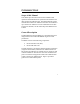
INTRODUCTION Scope of this Manual This manual provides instructions for the installation and operation of the Distributed I/O system Piccolo Interface Unit (PIU) and Piccolo XR Plus units. The Distributed I/O System includes PIUs and Piccolo XR Plus. Each PIU can be linked to up to 256 Piccolo XR Plus. For more information on the PIU and Piccolo XR Plus, see the online help of the DIOS Service Toolkit.
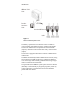
Introduction IRRInet Field Unit Piccolo Interface Unit RS485 or RS232 PIU Piccolo XR Plus Units I/O's Figure 1 DIOS –General System View The battery-operated Piccolo XR Plus unit is available in various models with different options of Inputs and Outputs. The Piccolo XR Plus unit can operate DC latch solenoids (outputs), read status and calculate flow of dry contact meters (inputs). The units are equipped with built-in radio for communication with the PIU.
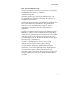
Introduction PIU - Piccolo Interface Unit The Piccolo Interface Unit (PIU; see Figure 2) is connected to the IRRInet Field Unit (FU) via RS232 or RS485 serial ports. Each PIU supports up to 256 Piccolo XR Plus units, with any available I/O combination, limited by the capacity of the IRRInet software only. Utilizing the S&F technology and networking capabilities, the PIU can be linked to Piccolo XR Plus units positioned in distances of up to 1500-2000 meters (approx.
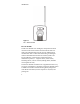
Introduction Figure 2 PIU – General View Piccolo XR Plus The Piccolo XR Plus is an intelligent, microprocessor based unit that can be used to monitor and control local units in a multi- unit communication network. Piccolo XR Plus units communicate data to a PIU while functioning as intelligent nodes in Distributed I/O monitor and control systems. The Piccolo XR Plus is often used in irrigation and water distribution systems (i.e.
Introduction Figure 3 Piccolo XR Plus – General View Safety Handling Instructions For safety handling instructions, see the Product Safety and RF Energy Exposure Booklet for PIU and Piccolo XR Plus Units, Motorola publication no. 6802974C70, which is distributed with the devices. The radio frequency band used by the DIOS system has not been harmonized throughout the entire European Economic Area (EEA).
Introduction This page left intentionally blank.
INSTALLATION General SAFETY SUMMARY ! Caution ! Caution The PIU and Piccolo XR Plus must be installed by qualified and authorized technicians, specifically qualified to handle high voltage if the installation involves high-voltage connections/installations. If the PIU will be installed outdoors, an outdoor plastic enclosure complying with UL60950 standard clause 6 is required. Note! See Piccolo XR Plus Screw Mounting Options (page 20) for mounting details.
Installation PIU Installation PIU Dimensions The unit dimensions are (see Figure 4): Width – 4.25" (108 mm), 4.96” 126 mm 11.46 " 291.1mm Height – 4.96" (126 mm), Height including antenna – 11.46" (291.1 mm), Depth – 1.67" (42 .6mm), Weight – 0.558 lb (253g) maximum.
Installation Before installing the PIU, verify that there is sufficient space around the unit according to the specific installation. Mounting the PIU On A Wall Using Screws 1. Secure two screws (not supplied) of maximum 0.37" (9.5 mm) head size to the wall, 3.256" (82.7 mm) apart. The wall-mounting template in Appendix D can be used to determine the space between both screws. 2. The screws must not protrude from the wall surface by more than 0.23” (6 mm) or by less than 0.16" (4 mm). 3.
Installation Mounting the PIU Using a Bracket 1. Using four M3x6 or M3x8 screws, attach a bracket (not supplied) to the back of the PIU. The upper two bracket holes must be 3.19" (81 mm) apart, and the lower two bracket holes must be 2.40" (61 mm) apart and 2.13" (54 mm) below the upper holes, as shown in Figure 6. 2.13" 54mm 2. Attach the bracket to the mounting surface. 2.
Installation PIU DIN Rail Mounting To mount the PIU on a DIN rail (not supplied), slide the PIU onto the rail at the grooves on the back of the unit. See Figure 7 and Figure 8.
Installation PIU Electrical Connections NOTE! Verify that all power connections are made in accordance with the applicable local standards. PIU Ground Connections Use the FKN8254B cable to connect the grounding cable directly to the TB connector of the PIU as shown in Figure 9. NOTE! The grounding connector is also used as an ON/OFF switch, and the unit cannot be powered on without connecting it.
Installation Power Connection The PIU can be powered by various types of supply sources: Internal (9VDC) battery; External 6V or 12V DC battery; Motorola power supplies – controllers. For example: IRRInet XL, IRRInet XM, IRRIcom, MOSCAD; 24VAC. NOTE! The unit DC voltage range is 6 to 16 volts. 9VDC Internal Battery Incorrect replacement of the battery can result in explosion! Replace only with the same or with an equivalent type of battery recommended by the manufacturer.
Installation Installation of an Internal Battery 1. Release the screw at the top of the battery chamber door, and slide the door out, as shown in Figure 10. 2. Connect the 9V battery cable (FKN8204B) to the DC power input connector on the back of the unit. 3. Connect the 9V DC battery to the cable. 4. Place the 9V DC alkaline battery in the chamber as shown in Figure 10. 5. Close the battery chamber door and secure with the screw.
Installation External Battery Power Connections ! The unit must be powered by a limited power source (12V DC) in accordance with standard UL/IEC 60950-1. See Power in Appendix A below. This connection is used for normal operation of the PIU, when radio communication is required, or when RS485 or RS232 ports are used. 1. Release the screw at the top of the battery chamber door and slide the door out, as shown in Figure 10. 2.
Installation External Power Supply Connections Use the applicable cable from the V152AH PIU installation kit to connect the PIU to Motorola standard controller power supply. 1. Release the screw at the top of the battery chamber door and slide the door out, as shown in Figure 10. 2. Connect one end of the cable to the DC power input connector on the back of the unit. 3. Connect the other end of the cable to the power supply output of a Motorola controller. 4.
Installation 24VAC Power Connections ! Caution ! The PIU must be connected to a power source equivalent to one or more of the following: a. A listed Direct plug-in unit. b. A Class II power source (defined by the National Electrical Code (NEC) and the Canadian Electrical Code (CEC). c. A power source that complies with UL1950 C1.2.1 or UL60950 C1.2.5. The unit must be powered by a limited power source (24V AC) in accordance with the UL/IEC 60950-1 standard. See Power in Appendix A below. 1.
Installation PIU Antenna Connection Flexible Antenna: Attach the flexible monopole antenna to the antenna connector at the top of the unit. See Appendix C for detailed information. Pole Antenna: Attach the FKN8258B antenna cable to the antenna connector at the top of the unit. Connect the other end of the antenna cable to a customer-supplied pole antenna. See Appendix C for detailed information.
Installation Piccolo XR Plus Installation Piccolo XR Plus Dimensions The unit dimensions are (see Figure 13): Width – 4.6" (117 mm) Height – 5.00" (127 mm) Hight including antenna – 11.46" (291.1 mm) Depth –2.67" (67.8mm) Weight – 0.54 lb (240 gr) maximum.
Installation The Piccolo XR Plus unit can be attached to any vertical or horizontal surface using screws. Before mounting the Piccolo X R Plus, verify that sufficient clearance is left around the unit. Allow 8" (20 cm) clearance off the bottom of the Piccolo XR Plus case for the user cable and 6.3" (16 cm) off the top of the unit for the flexible antenna. Piccolo XR Plus Screw Mounting Options Mount the Piccolo XR Plus on a vertical surface as follows: Secure the unit to any vertical surface using one 0.
Installation 54 mm A B C 98mm 49mm Figure 14 Piccolo XR Plus Mounting Screw holes – Back View Figure 15 Piccolo XR Plus Mounting Options 2
Installation Piccolo XR Plus Electrical Connections NOTE! Verify that all power connections are made in accordance with the applicable local standards. User Cable- 11.0558 P1 User Cable- 11.0559 P2 Figure 16 Piccolo XR Plus Ground and DC Power Connections Piccolo XR Plus Ground Connections Connect the yellow wire (17) of the 11.0558 user cable to the PGND, as shown in Figure 16.
Installation Power Connections ! The unit must be powered by a limited power source (6V DC) in accordance with standard UL/IEC 60950-1. See Power in Appendix A below. The Piccolo XR Plus is powered by an external 6V DC battery source. Use the 11.0558 and 11.0559 cables to connect the Piccolo XR Plus to an external battery. Connect Wire #1 (red) to the positive (+) pole of the battery through a 1A fuse (not supplied) and wire #2 (black) to the battery negative (–) pole. See Figure 16.
Installation User Cable-11.0558 Solenoids Up Up to 8 Output Common Wire (9) Gray Sensors up to 12 Input Common Wire (6) Green Figure 17 Piccolo XR Plus I/O Connections NOTE! 2 For proper operation, the Piccolo XR Plus unit must be connected either to a flexible antenna or to a pole antenna. See Appendix C for antenna installation details.
Installation Table 1: Connector P1 – Primary Pin assignment of the Piccolo XR Plus user cable (11.0558) Connector TAG COLOR DESCRIPTION + Red Battery 6V (+) - Black Battery 6V (–) 2 Green Output 2 9 White / Black Input 4 10 White / Gray Input Common (1-4) 3 Brown Output 3 4 Purple Output 4 5 Gray Output Common (1-4) 1 Blue Output 1 6 White / Blue Input 1 7 White / Green Input 2 8 White / Purple Input 3 31 Orange Comm. 1 (to 31 P2) 32 White Comm.
Installation Table 1: Connector P2 – Secondary Pin assignment of the Piccolo XR Plus user cable (11.
THE DIOS PIU AND PICCOLO XR Plus UNITS PIU Overview The PIU unit (see Figure 18) is comprised of the following: Internal radio interfaces and a radio modem A logic board Communication ports LEDs 24V AC PGND/ RS485 Pwr IN DC Switch Adaptor Port RS232 Figure 18 PIU Unit General View 27
The DIOS PIU and Piccolo-XR Units DC Power In Figure 19 PIU Unit DC Power Connection– Rear View PIU Communication Ports The PIU has four ports: NOTE! Only one of the two RS ports (232 and 485) can be operated at a time, i.e. they do not operate together. 28 RS485: Communication between multiple PIU units and the FU. RS232: Communication between the PIU and the FU; Configuration Port (unit programming and monitoring). Adapter port: Communication with and programming the Piccolo XR Plus units.
The DIOS PIU and Piccolo-XR Units PIU Connectors The PIU connectors (see Figure 18): RS232 (RJ45, 8 pin) RS485 Adapter port PGND And Power Switch 24 V AC PWR IN 6, 9, 12 V DC Battery Input (RJ10, 4 pin) (RJ10, 4 pin) (TB 3 pin) (2 pin) (2 pin) PIU LED Operation Three software programmable LED indicators are located on the PIU enclosure (see Figure 18). These indicators can be used for diagnostics purposes.
The DIOS PIU and Piccolo-XR Units PIU Adapter Operation The PIU can be used as an adapter to perform the following functions: Communicating with the Piccolo XR Plus for configuration, monitoring or hardware test. Downloading new software to a Piccolo XR Plus unit. Downloading new software to a PIU unit. Communicating With a Piccolo XR Plus Unit 1. Connect the PIU adapter RS232 port to the computer with the FTN6597B cable (see Figure 20). 2.
The DIOS PIU and Piccolo-XR Units Piccolo XR Plus + - PIU Adapter +- P5 P4 Communication Cable Toolkit Laptop RS232 RS232 to PC Connectors GND RS485 Adapter To Piccolo XR Plus Figure 20 PIU Adapter – Piccolo XR Plus Communication Mode Connections NOTE! The grounding connector is also used as an ON/OFF switch, and the unit cannot be powered on without connecting it. (See Figure 9.
The DIOS PIU and Piccolo-XR Units Downloading new software to a Piccolo XR Plus unit 1. Connect the PIU adapter RS232 port to the computer using the FTN6597B cable (see Figure 21). 2. Connect the PIU adapter unit to an external 12VDC battery or to an internal 9V battery. (See page 12 for power options). 3. Connect the Piccolo XR Plus unit to an external 6 V DC power source. (See Power Connections on page 23.) 4.
The DIOS PIU and Piccolo-XR Units Communicating with a PIU unit 1. Connect the PIU unit RS232 port to the computer with the FTN6597B cable (see Figure 22). 2. Connect the PIU unit to an external 12VDC battery or to an internal 9V battery. (See page 12 for power options.) 3. Use the Distributed I/O Service Toolkit for configuration, monitoring or hardware test. For additional information, please refer to the online help of the DIOS Service Toolkit.
The DIOS PIU and Piccolo-XR Units Downloading new software to a PIU 1. Connect the PIU adapter RS232 port to the computer with the FTN6597B cable (see Figure 23). 2. Connect the PIU adapter to an external 12VDC battery or to an internal 9V battery. (See page 12 for power options). 3. Connect the PIU unit to an external 12VDC battery or to an internal 9V battery. (See page 12 for power options.) 4.
The DIOS PIU and Piccolo-XR Units Piccolo XR Plus Overview The Piccolo XR Plus Remote Terminal Unit (RTU) is comprised of: Logic board, which includes: I/O’s Radio interface Power supplies Communication ports Radio 2*26 PIN Connector P1+P2 Figure 24 Piccolo XR Plus Unit Piccolo XR Plus Communication Ports The Piccolo XR Plus has three ports: Programming port: for downloading SW.
The DIOS PIU and Piccolo-XR Units Piccolo XR Plus Connector The Piccolo XR Plus has two D-type 26 pin connector (see Figure 24). See Table 1 and Table 2 on pages 25–26 for more information Input/Output options A variety of I/O options is available for use with the Piccolo XR Plus, increasing the system flexibility. The available Piccolo XR Plus I/O options are: 5 DI / 5 DO 6 DI / 6 DO 8 DI / 8 DO 11 DI / 5 DO 12 DI / 4 DO For option numbers, see Appendix B below.
APPENDIX A: PIU and PICCOLO XR Plus SPECIFICATIONS PIU Specifications Environmental Operating Temperature -30 C to +60 C (-22 F to +140 F) Storage Temperature -40 C to +85 C (-40 F to + 185 F) Relative Operating Humidity Operating Altitude 0 to 95% without condensation @ +50 C (122 F) -400 m to +4000 m (-1300 ft to 13,000 ft) above sea level Mechanical Dimensions 126x108x42.6 mm 1 mm (4.96"x4.25"x1.67") Weight 253 gr 25 gr (0.56 lb 0.
APPENDIX A: PIU AND PICCOLO-XR SPECIFICATIONS PIU Board Communication Ports RS232 Serial RS-232 RS485 Multi Drop 2 Wire Adapter Serial interface between PIU as adapter and PICCOLO–XR Plus (UART levels) Boot-Strap Software programming port Internal Radio RF Frequency UHF 450–470 MHz (actually 450.0125-469.9875) OR UHF 430-450 MHz (actually 430.0125-449.9875)* ** (Service Toolkit programmable) Duty Cycle ratio < 10% (relative to a 1 hour period for ISM band only) Channel spacing 12.
APPENDIX A: PIU AND PICCOLO-XR SPECIFICATIONS TX deviation: 2KHz 15% RX BER LEDs BER<1% (See Note 5 on p. 41.) Red, Orange, Green (SW Programmable) Power Input Voltage External Source (DC Power In) 6.00 to 16.00 VDC e.g. lead acid battery or solar panel, typically used in irrigation systems. External Source (24V ~ IN) 24VAC±20%, typically from transformer to 110VAC or 220VAC. Power Modes Adapter Mode (Using the internal 9 V battery) Normal Operation 1 – 5 mA (See Note 4 on p. 41.
APPENDIX A: PIU AND PICCOLO-XR SPECIFICATIONS PIU Mode (Using a 12 V or 6 V external power source) Radio Transmission (TX power-10 mW) 25 – 40 mA 65 – 90 mA (PWR IN =14 V) (PWR IN = 6 V) (TX power-100 mW) 30 – 65 mA 85 – 135 mA (PWR IN =14 V) (PWR IN = 6 V) 13 – 18 mA 30 – 38 mA (PWR IN =14 V) (PWR IN = 6 V) Standby current Radio Receives Sleep Mode LPM0 LPM3 200 – 320 μA (See Note 2 on p. 41.) 130 – 250 μA (See Note 2 on p. 41.
APPENDIX A: PIU AND PICCOLO-XR SPECIFICATIONS Note 1: Power In = 9 V DC (Adapter), RS232 = shutdown, RS485 = disable, Radio (On Board Circuits) = off, internal Radio is off. RS232 cable connected. Note 2: Power Supply = 14 V DC (PIU), RS232 = shutdown, RS485 = disable, Radio (On Board Circuits) = off, internal Radio is off. RS232 cable connected. Note 3: Power In = 5.4 V DC (Power fail), RS232 = shutdown, RS485 = disable, Radio (On Board Circuits) = off, internal Radio is off. RS232 cable connected.
APPENDIX A: PIU AND PICCOLO-XR SPECIFICATIONS Mechanical Dimensions 127x117x67.8 mm 1 mm (5.00"x4.60"x2.67") Weight 240 gr 24 gr (0.54 lb 0.
APPENDIX A: PIU AND PICCOLO-XR SPECIFICATIONS Internal Radio RF Frequency UHF 450–470 MHz (Service Toolkit programmable) Duty Cycle ratio < 10% (relative to a 1 hour period for ISM band only) Channel spacing 12.5 KHz Internal Modem DPSK 1200 TX RF Low power mode: 8 – 12 mW @+25 C (+77 F) (10 mW typical) 5 – 16.3 mW @–30 C - +60 C (-22 F to 140 F) TX RF High power mode: 80 – 108 mW @+25 C (+77 F) (100 mW typical) 50 – 108 mW @–30 C - +60 C Frequency Error 1.
APPENDIX A: PIU AND PICCOLO-XR SPECIFICATIONS Radio Transmission Radio Off 1.2 – 1.5 mA (See Notes 6, 7 p. 44.) (TX power-10mW) 65 – 90 mA (TX power-100mW) 100 – 150 mA (See Notes 8, 9 p. 44.) Radio Receives 30 – 40 mA (See Notes 8, 9 p. 44.) (See Notes 8, 9 p. 44.) Sleep Mode LPM0 LPM3 Power Fail Mode LPM3 190 – 250 μA (See Note 7 p. 44.) 40 – 65 μA (See Note 7 p. 44.) 40 – 70 μA (See Note 6 p. 44.
APPENDIX A: PIU AND PICCOLO-XR SPECIFICATIONS Note 11: For radio functionality external Power In minimum voltage=5 V. Note 12: Please note that due to the lower transmission power, the distance between the Piccolo and the PIU is shorter than the distance when using a licensed frequency with 100 mW transmission power. Note 13: The current consumption of the Piccolo will increase due to the fact that the Maximum transmission time is reduced and therefore the Piccolo should wake up more frequently.
APPENDIX A: PIU AND PICCOLO-XR SPECIFICATIONS Regulatory Standards US and Canada Grant of Equipment Authorization IMPORTANT: Unauthorized repairs or modifications could result in permanent damage to the equipment and void your warranty and your authority to operate this device under Part 15 of the FCC Rules. FCC Grant of Equipment Authorization FCC ID: 2APCUMO515A This Class B digital apparatus complies with Canadian ICES003.
APPENDIX A: PIU AND PICCOLO-XR SPECIFICATIONS Piccolo XR Plus Units, Motorola publication no. 6802974C70, which is distributed with the devices. European Union Notification The CE mark is the official marking required by the European Community for all Electric and Electronic equipment that will be sold, or put into service for the first time, anywhere in the European community.
APPENDIX A: PIU AND PICCOLO-XR SPECIFICATIONS FCC Warnings This device has been tested and found to comply with the limits for a Class B digital device, pursuant to Part 15 of the FCC Rules. These limits are designed to provide reasonable protection against harmful interference in residential installations. This equipment generates uses and can radiate radio frequency energy and, if not installed and used in accordance with the instructions, may cause harmful interference to radio and television reception.
APPENDIX B: MODELS and ACCESSORIES General The following tables describe the available models, options and accessories. DIOS Models Model Piccolo Interface Unit (PIU) F4604B Piccolo XR Plus DC F4614B PIU Options Option ADD: RS-485 Option (indoor) V440AD ADD: RS-232 Cable 3 m V666AA ADD: UHF Antenna for PIU V208AJ ADD: PIU Adapter V345AM ADD: PIU DIOS Application V377AD INT: 12.
Appendix B: Models and Accessories Piccolo-XR Plus Options Option ADD: 5 DI / 5 DO Option XR Plus 5/5 ADD: 6 DI / 6 DO Option XR Plus 6/6 ADD: 8 DI / 8DO Option XR Plus 8/8 ADD: 11 DI / 5 DO Option XR Plus 11/5 ADD: 12 DI / 4 DO XR Plus 12/4 ADD: UHF Antenna for Piccolo–XR V208AH INT: 12.
APPENDIX C: ANTENNA General The PIU and Piccolo XR Plus units can be connected either to a flexible or to a pole antenna. The antenna connector (see Figure 25), located at the top of the unit, is used for both antenna types. Antenna SMA Connector Antenna SMA Connector Figure 25 PIU and Piccolo XR Plus Antenna Connectors Flexible Antenna Specifications Frequency Range: Polarization: Nominal Impedance: VSWR: Power Rating Temperature Range: UHF Vertical 50 ohms 1.
Appendix C: Antenna Pole Antenna The pole antenna installation must comply with the following requirements in order to ensure optimal performance and guarantee that human exposure to radio frequency electromagnetic energy is within the guidelines set forth by the applicable local regulations. The antenna must be mounted outdoors, preferably on a tower, if possible. Building mounted antennas must be located on the building roof.
Appendix C: Antenna Pole Antenna installation SMA to SMA option Antenna Antenna Support Rubber Washer Nut Lock Washer SMA Connector Adjustable Straps SMA to SMA Antenna Cable Rubber Sleeve SMA Connector Figure 27 SMA to SMA type PIU/Piccolo XR Plus Pole Antenna 1. Connect a flexible antenna to the antenna support plate using rubber washers, lock washer and a nut (see Figure 27). 2. Connect one end of the SMA Cable to the antenna connection. 3. Connect the other end to the PIU/Piccolo XR Plus.
Appendix C: Antenna SMA TO N-TYPE Antenna Antenna Support Rubber Washer Nut Adjustable Straps Nut Lock Washer SMA Connector N-Type Connector SMA to N-Type Antenna C a b l e N-Type Washer Figure 28 SMA to N-Type Pole Antenna 1. Connect a flexible antenna to the antenna support plate using rubber washers, lock washer and a nut (see Figure 28). 2. Connect the SMA end of the cable to the antenna connection. 3. Connect the N Type end to the PIU/Piccolo XR Plus.
Appendix C: Antenna Pole Antenna Dimension 83mm 200mm 91.5mm 174mm Figure 29 shows recommended dimensions for a supporting plate for the pole antenna.
Appendix C: Antenna This page left intentionally blank.
APPENDIX D: PIU/Piccolo XR Plus MOUNTING TEMPLATES Use the following template for PIU wall mounting. 3.26" 82.
Appendix D: PIU/Piccolo XR Plus Mounting Templates 1.93" 49mm 3.86" 98mm The following is a template that can be used for mounting the Piccolo XR Plus unit.
MOTOROLA and the Stylized M Logo are registered in the U.S. Patent and Trademark Office. All other product or service names are the property of their respective owners.