TRANSTECH III Transmission Service System Part No. 500-1100P USER MANUAL UNIT EQUIPPED WITH V-2 CONTROL BOARD 1324 Blundell Rd. Mississauga ON Tel. 905.615.8620 Fax. 905.615.9745 www.motorvac.
Table of Contents Page Introduction ...............................………….....…………………………..................................................... 1 Overview ………………............................................………………………………............…….………… 2 System Features and Functions ………..…………………………………………….....................………… 3-4 Front View - Control Panel Features and Functions …..………....….....……............................... 3 Right Side Features ….……………………….……………….………………................................
Introduction Congratulations on your selection of the TRANSTECH III Transmission Service System. By choosing this product, you are acquiring the most technologically advanced method available for automatic transmission service and fluid exchange. The TRANSTECH III System is a self-contained system; designed to connect to any automatic transmission through its cooling system lines.
Overview This manual contains all the information you need to use the TRANSTECH III system. Please make sure all technicians using the unit read this manual and have it within easy reach whenever the unit is being used. The following is a quick reference to the information in this manual: System Features and Functions This chapter describes the TRANSTECH III Transmission Service System’s Switches, Lights and Connections.
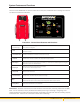
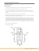
System Features and Functions The front of the TRANSTECH III cabinet contains the control panel, the fluid fill neck for adding new transmission fluid and the fluid level windows. A B C G H D E F I J Front View - Control Panel Features and Functions A. Start / Resume (Fluid Exchange) Begins service - Starts exchanging new fluid for used fluid. NOTE: With DRAIN, FILL, and ENGINE START light on, service is in progress. B. Drain Drains fluid from vehicle’s transmission.
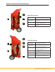
System Features and Functions (Cont’d) C Right Side Features A D B A. Output Hose Connects to the transmission’s cooling system. B. Quick Coupler Secures the unit’s output hose connection to the adapter connected to the vehicle’s transmission cooling system. C. Serial Plate dentifies the unit’s model and specific manufacturer’s production number. D. Battery Cables Positive (red) and negative (black) battery connections. D Left Side Features A E C B F 4 A.
Theory of Operations Descriptions of the various operations, control buttons, and indicators that make up the control panel are listed below. OFF MODE: • When the unit is connected to power, an alarm will sound indicating power-up, all LED’s will flash on and off and then the ENGINE START light will be flashing.
Theory of Operations SPECIAL CONTROL FEATURES: PRESS AND HOLD MODES: Press and hold these buttons for five seconds to enable special functions. RESET MACHINE: press and hold STOP button for 5 seconds will cause a ‘reset’ of the control board. (This will do the same as disconnecting the power cord). MANUAL EMPTY WASTE: Press and hold the EMPTY WASTE button for 5 seconds to enable manual control of the waste pump.
Safety Information and Precautions (Cont’d) 22. 23. 24. 25. 26. 27. 28. 29. 30. 31. 32. 33. 34. 35. 36. 37. 38. 39. 40. 41. 42. 43. 44. 45. 46. 47. 48. Use with adequate ventilation. Avoid breathing vapors. Do not store chemicals in or on the machine (other than automatic transmission fluid). Improper use of transmission fluid can cause injury. Over exposure can have harmful effect on eyes, skin, respiratory system and possible unconsciousness and asphyxiation. Improperly blocked vehicles can move.
TransTech III Auto-Prime Procedure (For first time set-up only) Set-Up Instructions: 1. Check the output/return hoses, battery connections, and all external components for damage. 2. Fill the CLEAN FLUID tank with approximately 6 quarts (5.7 liters) of new ATF. 3. Connect two compatible adapters to each other, secure tightly. Attach the CLEAN FLUID & INLINE RETURN hoses together using the connected adapters. Ensure that both hoses have no kinks or visual damage. 4.
Transmission Service Procedure Follow the steps below to connect the unit to the vehicle’s transmission cooler lines. Make sure the vehicle has at least 1/8 tank of fuel before beginning this process. IMPORTANT Do not perform the transmission service if the vehicle’s engine oil or coolant level is low. If necessary, add motor oil and/or coolant. Do not perform service if new transmission fluid is below 50 degrees Fahrenheit.
Transmission Service Procedure (Cont’d) 3. Locate and disconnect the cooler line at the easiest connection point and install adapters: a) At cooler line connection to radiator. Connection is usually accessible from the top corner of the radiator (could be on either top side). b) At clamped rubber hose connection to transmission cooler (connections are usually accessible from the under side of the vehicle (cooler is usually in front of radiator). c) At cooler line connecting to the transmission. 4.
Transmission Service Procedure (Cont’d) 8. With the vehicle’s engine still running, the ENGINE START light should be ON solid. The PRESSURE GAUGE will be reading the amount of pressure coming from the vehicle. Check the transmission fluid level. Feel the hoses for heat. Heat in both hoses will verify good bypass flow from vehicle, through the unit and back to vehicle. Transmission fluid will automatically circulate in bypass mode until service is begun. Press the CHANGE FLUID button.
Transmission Service Procedure (Cont’d) Optional Transmission Filter Change:Pan Drop Style Service Procedure. If the vehicle’s transmission pan filter is to be replaced, perform the following steps. a) Follow steps 1 thru 7 then press the DRAIN button on the unit’s control panel. Let the engine run until the unit’s alarm sounds and the LOW VEHICLE FLUID and ENGINE STOP and ENGINE START lights are flashing.
Frequently Asked Questions 1. How is the CLEAN FLUID tank completely emptied in order to change fluid type? The TransTech III clean tank can be completely emptied. First connect the positive battery cable to a battery’s positive post. Connect the negative battery cable to the battery’s negative post. Install an adapter into the unit’s clean side hose. Insert the hose with adapter into a suitable container and tip the unit back slightly.
Maintenance Procedures The following maintenance procedures should be performed on a routine basis: 1. Carefully clean the exterior with a soft cloth to keep the cabinet looking new. Check the cabinet for dents or impact markings, if found, inspect for damaged components. 2. Check all hoses and wires for cuts or frays. 3. Clean the unit’s filter screens after every 100 services or 6 months, which ever comes first. Cleaning the Unit’s Filter 1. Disconnect power harness from power source. 2.
Troubleshooting and Additional Help Refer to the list below troubleshooting assistance. Problem Possible Cause 1. Unit does not power-up. No LED’s are illuminated Polarity is reversed on vehicle battery connection. Check connection to battery for a loose condition. Circuit breaker may be tripped. (Automatic reset). Faulty battery 2. Start light does not stop blinking when the engine is started. Observe pressure gauge to see if fluid/pressure is reaching the machine.
Error Alerts The TransTech III has been designed to stop the service and alert the operator in certain instances if the unit is not functioning properly. See below for details. Alert Notification Fill Error The alarm sounds. See Figure Below. The following LEDs flash: FILL. Cause Hardware Troubleshooting steps Recovery There is a hardware or software problem that has caused the unit to lose track of how much fluid is in the Clean Tank.
Description Picture ID Mark Vehicles Deluxe Adapter Kit 200-3101A Mating Part Standard Adapter Kit 200-3100A 11/22/13 In Euro Kit 2003120 TransTech System Accessories 1 060-0450 Hose Clamp 7/8” I.D.
Description 060-2110 NA Adapter Trans Opel Corsa Picture ID Mark Vehicles 110 Opel Corsa Deluxe Adapter Kit 200-3101A Mating Part Standard Adapter Kit 200-3100A 11/22/13 In Euro Kit 2003120 TransTech System Accessories 1 1 060-2300 14 mm Female 060-2402 060-2740 14mm x 1.5 Banjo Euro / Asia Vehicles 060-2600 060-2300 060-2700 16mm x 1.5 Bubble Flare European Vehicles Union - M 14mm X 16mm European Vehicles 2 1 1 1 1 060-2700 060-2740 060-2402 14mm x 1.
Mating Part Description 062-2061 062-2062 Volvo 850 Application, Volvo V-70 All Wheel Drive Male O-Ring Type / Flange Style Volvo 850 Application, Volvo V-70 All Wheel Drive O’Ring P/N: 080-3602 062-2062 062-2061 Volvo 850 Application, Volvo V-70 All Wheel Drive Female receptacle / Flange Style Volvo 850 Application, Volvo V-70 All Wheel Drive 062-2064 Volvo ‘S’ Series Application Male O-Ring Type / Push Lock Style Volvo ‘S’ Series Application Volvo 'V' & 'XC' O'ring:P/N 080-2326 1 062-2063 0
Appendix C – Parts Service Parts for the TRANSTECH III Transmission System. Please refer to the part numbers below when ordering parts.
21 info@motorvac.com www.motorvac.
ZIM10-00290 Rev5 1324 Blundell Rd. Mississauga ON Tel. 905.615.8620 Fax. 905.615.9745 www.motorvac.