
Digital Return Transmitter Installation Sheet


STARLINE 7
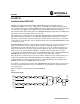
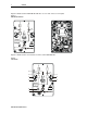
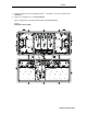
Figure 7 illustrates the 2X redundant return configuration board. Jumpers J5 and J6 are shown
in the normal default position. Jumper
J6 enables/disables signal flow to output connector
J8 (Tx2). Jumper J5 terminates input connector J3 (IN2) when only a single RF input is used.
Figure 7
2X redundant return configuration board
J9
T3
Q1
C15
R1
J4
J1
J2
C9
T1
J5
J6
C10
TERM
TERM
J7
J8
C11
R7
T2
C12
J3
IN1IN2
TX2
TX1
R2
R11
C5
C4
R13
R16
R10
R4
C7
C8
C13
C6
R3
R8
R5
R12
C18
R14
R15
L1
C16
C19
C14
C17
R6
C2
C1
C3
SM
J5 J6
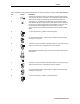
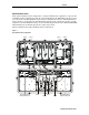
Figure 8 illustrates the signal flow through the 2X redundant return board:
Figure 8
2X redundant return board- signal flow
Loss = 0.9 dB
J6
-0.5 dB
-3.5 dB
+7.5 dB
-3.5 dB
TX2
TX1 SM
J5
IN2
IN1
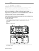
To set up the split return option:
1 Confirm that the SG4-DRT-2X is installed in lid optics slots 3 and 4, or 5 and 6.
2 Confirm that a 2X redundant return board is installed in lid return configuration board
locations 2 and 3 as illustrated in Figure 5.
3 Position J6 in the right-most position to terminate the output to transmitter two.
4 Connect an RF cable from the 2X redundant return board, in lid return configuration board
location 2, to CH B of the SG4-DRT-2X .
5 Connect an RF cable from the 2X redundant return board, in lid return configuration board
location 3, to CH A of the SG4-DRT-2X.
The RF cables should be approximately eight inches long and have red boots on the
connector signifying the return path.
6 If necessary, connect the appropriate return RF cables from the SG4-RF modules to each 2X
redundant board.
SG4-DRT-2X Installation Sheet