
Digital Return Transmitter Installation Sheet
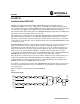


6 STARLINE
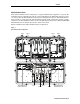
Split Return
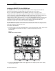
In the split return configuration, each pair of RF returns is applied to a separate 2X redundant
return configuration board. In a typical installation, the RF modules in Ports 1 and 3 are
connected to the 2X redundant return board in return configuration location 2. The RF modules
in Ports 4 and 6 are connected to the 2X redundant return configuration board in configuration
location 3. The 2X redundant return configuration board, in location 2, directs RF to CH B of the
SG4-DRT-2X. The 2X redundant return configuration board, in location 3, directs RF to CH A of
the SG4-DRT-2X. The same configuration board is used in the split redundant return
configuration explained in the next subsection.
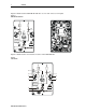
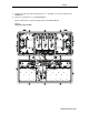
Figure 6 illustrates the split return configuration:
Figure 6
Split return configuration
2X DIGITAL TRANSMITTER
CH BCH A
-5 dBm V
NOMINAL
TOTAL POWER
-5 V/m W
ENABLE/FAULT
-5 dBm V
NOMINAL
TOTAL POWER
J
X
P
J
X
P
A / DA / D
INVISIBLE LASER
RADIATI ON. AVOID
EXPOSURE TO BEAM.
CLASS 3B L ASER
PRODUCT.
Port 1 Port 6
Split Return
Configuration board
location #
2
Split Return
Configuration board
location #3
CH A CH B
Port 3 Port 4
SG4-DRT-2X Installation Sheet