
Computer Hardware User Manual

1 Preparation and Installation
PrPMC800/800ET Processor PMC Module Installation and Use (PrPMC800A/IH5)
5
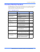
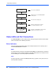
Harrier Power-Up Configuration Header
A 2mm, 16-pin low profile header located on side 1 of the PrPMC800/800ET provides the
means to change some of the Harrier power-up configuration settings. The pin assignments for
this header, along with the power-up setting with the jumper on or off, are as follows (boards are
shipped with all jumpers off):
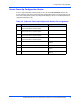
Table 1-4. J2 Harrier Power-Up Configuration Header Pin Assignments
J2 Jumper On Jumper Off
1-2 PUST0 = 0
Harrier PUST Bit 0 in GCSR Register.
PUST0 = 1
3-4 PUST1 = 0
Harrier PUST Bit 1 in GCSR Register
PUST1 = 1
5-6 PUST2 = 0
Harrier PUST Bit 2 in GCSR Register
PUST2 = 1
7-8 PUST3 = 0
Harrier PUST Bit 2 in GCSR Register
PUST3 = 1
9-10 Hold off Configuration Space access Configuration Space access
enabled
11-12 Processor held in reset at power-up Processor enabled at power-up
13-14 Class Code set for I2O Controller” Class Code set for “Bridge
Device”
15-16 Xport 1uses normal data byte ordering Xport 1 uses Hawk data byte
ordering