
User guide

9
This library module has two parameters:
• IrDA_Speed_bod - IrDA transmitting rate, 9600 bod by default;
• Clock_Freq_Hz – on-board clock frequency, 25175000 Hz by default.
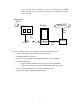
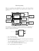
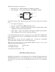
Next library module, Time Intervals Measurement Unit (above figure), has following
ports:
• clk – input clock frequency;
• temp_inp – signal from the TMP04 temperature sensor;
• measure – when “1”, updates internal registers temp1 and temp2 with the results
of high-period and low-period measurements;
• temp1, temp2 – outputs of the internal 12-bit registers which hold the measured
value for high-period and low-period signal measurements.
Control Unit synchronizes the work of the previous two modules. The communication
protocol it implements (that works over IrDA Physical Layer Protocol) is described later
in this chapter.
Display Decoder converts the least significant byte of temp2 into hexadecimal
representation that is displayed on the on-board 2-digit display.
The total size of the source code is approximately 200 lines, below is some of the
statistics reported by the synthesis tool:
Total logic cells used:
Total flipflops required:
Total product terms required:
123/128 ( 96%)
89
398
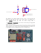
IrDA Physical Layer Protocol
Our FPGA board with sensor sends measured values to the Palm via infrared link using
IrDA Physical Layer protocol as a physical layer protocol and communication protocol
described in the next section that uses IrDA Physical Layer Protocol as an underlying
protocol.
clk
temp_inp
measure
Time
measur
tem
p
1
[
11:0
]
temp2[11:0]