
User guide

8
FPGA Programming
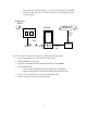
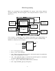
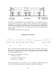
FPGA was programmed using MAX+PLUS II software with Verilog hardware
description language. The block diagram of the designed hardware is depicted on the
figure below.
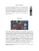
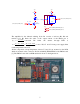
Clock Generator, Temperature Sensor, Infrared Transmitter and 2-digit Display are
located on/connected to the FPGA board and are external as regards to the FPGA chip.
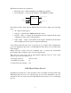
IrDA Protocol Generator has four inputs:
• clk – clock frequency input;
• byte_to_send – 8-bit data input;
• load – when load=1, input data are copied to the internal register from which they
will be send using IrDA protocol later;
• start – after setting this input to 1 the data from internal register are transmitted
via infrared LED using IrDA physical layer protocol;
• led_out – output to which infrared LED should be connected;
• tclk – output with IrDA_Speed_bod frequency.
Clock
Generator
IrDA Protocol
Generator
Time Intervals
Measurement
Unit
Control
Unit
2-digit
Display
Display
Decoder
Temperature
Sensor
Infrared
Transmitter
F
PGA
Library 1
Library 2
clk
byte_to_send [7:0
]
load
s
tart
IrDA
gen
led out
tclk