
User guide

7
+5V
Connector P1 (FPGA pin 10)
GND
GND
+5V
GND
27R2
0.047uF
C1
27R3
1.2 kR1
NTE3017
D1
Connector MAX_EXPANSION pins 3, 5
NTE2363
Q1
Connector P1 (FPGA pin 11)
+5V
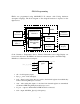
TMP04
U1
Dout
V+
GND
Connector MAX_EXPANSION pins 4, 6
22uF
C2
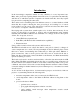
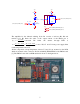
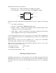
The amplifier for the infrared emitting diode D1 consists of resistors R1, R2 and
transistor Q1. R1 limits the value of the output current of the FPGA pin to
mA
R
VV
I
cc
outfpga
6.3
1
7.0
_ =
−
=
and R2 limits the current through LED to
mA
VVV
R
VVV
I
ledcc
led
115
27
2.07.15
2
2.0
=
−−
=
−−
=
. R3, C1 and C2 form power supply filter
for the temperature sensor U1.
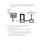
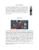
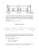
All the components except temperature detector U1 and C1 are mounted on the PCB,
which is mounted on the connectors P1, P3 and MAX_EXPANTION of the FPGA board
[1]. The FPGA board with our PCB attached is shown on the figure below.