
User guide

6
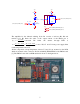
Infrared Transmitter
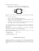
To send data to the Palm PDA via IrDA link, we used NTE3017 infrared
GaAs emitting diode (NTE Electronics, Inc.). Its emission wavelength is
950 nm, angle of half intensity is ±22 degrees and radiant power is 15
mW. The nominal continuous current of NTE3017 is 150 mA, while the
output current of FPGA I/O pin is only 25 mA [3]. That is why we had to
add a simple, one-stage amplifier (see schematics on the next page).
The infrared diode is mounted on the PCB connected to the FPGA board
(figure on the right).
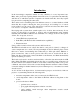
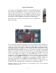
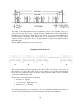
FPGA Board
For processing the signal from temperature sensor and sending the data to the Palm, we
used the University Program Design Laboratory Package made by Altera Corporation
(figure above). This board contains two FPGAs from MAX7000 and FLEX10K families,
several LED displays and switches, and the oscillator [1]. From the board we use only
MAX7000 family FPGA (EPM7128S) for processing the data, dual-digit 7-segment LED
display for controlling the changes in the temperature (it is displaying the hexadecimal
number, proportional to the low-period T2), and oscillator 25.175 MHz as the clock
source for the FPGA. We decided to use MAX7000 FPGA because it stores its
configuration in the internal EEPROM and does not require special programmer
hardware for external EEPROM or computer to download the configuration after power-
up. The internal EEPROM of EPM7128S is programmed via FPGA JTAG pins,
connected to the printer port of the IBM PC, under MAX+PLUS II software control.
FPGA EPM7128S contain 128 macrocells, each of it consists of one flip-flop and five
product terms. The equivalent number of usable gates for this FPGA is 2500.
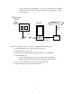
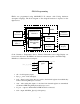
Schematic diagram for the interfacing of the temperature sensor and the infrared
transmitter is depicted below: