
User guide

5
Chapter 1. Description of the hardware used in the project
Temperature Sensor
We used TMP04FT9 temperature sensor made by Analog Devices. This sensor has a
wide temperature range (-40°C to +150°C) with the accuracy ±1.5°C (in -25°C to
+100°C range) [13]. The temperature detector has modulated serial digital output, with
the ratio of high and low period being directly proportional to the temperature of the
device. This significantly simplifies its interfacing to the microprocessorless FPGA
board, because it eliminates the need of ADC and calibration procedures (in comparison
with thermoresistor) and it doesn’t require implementing the two-way protocol in
hardware, which we would need to do if we used Dallas Semiconductors i-Button.
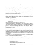
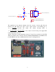
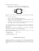
The output of the sensor is a square wave with the high and low periods T1 and T2 (see
the figure below):
The period T1 is approximately 5 - 15 ms, while T2 varies in 10 – 40 ms interval.
The temperature can be calculated using the following formulas:
Since both periods are obtained consecutively and the formulas depend
on their ratio only, the temperature readings are independent of the drift
in either originating clock in TMP04 or the clock of the FPGA board that
is used for the period measurements. The sensor is laser-trimmed for
accuracy and linearity during manufacture and do not require any further
calibration.
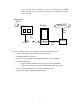
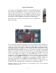
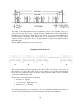
The model TMP04FT9 we use uses TO-92 package, which we mounted
on the separate PCB and connected with the main board using 3-wire
cable (see figure on the right).
×
−=
2
1400
235
T
T
e(C)Temperatur
×
−=
2
1720
455
T
T
e(F)Temperatur