
Network Device User Guide


Device User Guide — 9S12C128DGV1/D V01.05
115
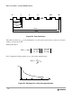
This is very important to notice with respect to timers, serial modules where a pre-scaler will eliminate the
effect of the jitter to a large extent.
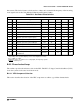
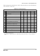
Table B-12 PLL Characteristics
Conditions are shown in Table A-4 unless otherwise noted
Num C Rating Symbol Min Typ Max Unit
1 P Self Clock Mode frequency
f
SCM
1 5.5 MHz
2 D VCO locking range
f
VCO
8 50 MHz
3D
Lock Detector transition from Acquisition to Tracking
mode
|∆
trk
|
34
%
1
NOTES:
1. % deviation from target frequency
4 D Lock Detection
|∆
Lock
|
0 1.5
%
(1)
5 D Un-Lock Detection
|∆
unl
|
0.5 2.5
%
(1)
6D
Lock Detector transition from Tracking to Acquisition
mode
|∆
unt
|
68
%
(1)
7C
PLLON Total Stabilization delay (Auto Mode)
2
2. f
OSC
= 4MHz, f
BUS
= 25MHz equivalent f
VCO
= 50MHz: REFDV = #$03, SYNR = #$018, Cs = 4.7nF, Cp = 470pF, Rs =
10K
Ω.
t
stab
0.5 ms
8D
PLLON Acquisition mode stabilization delay
(2)
t
acq
0.3 ms
9D
PLLON Tracking mode stabilization delay
(2)
t
al
0.2 ms
10 D Fitting parameter VCO loop gain
K
1
-100 MHz/V
11 D Fitting parameter VCO loop frequency
f
1
60 MHz
12 D Charge pump current acquisition mode
| i
ch
|
38.5 µA
13 D Charge pump current tracking mode
| i
ch
|
3.5 µA
14 C
Jitter fit parameter 1
(2)
j
1
1.1 %
15 C
Jitter fit parameter 2
(2)
j
2
0.13 %