
MC68VZ328 Integrated Processor User's Manual

AC Electrical Characteristics
Electrical Characteristics 19-31
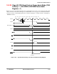
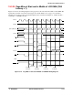
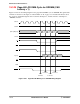
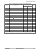
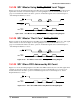
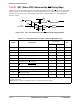
Table 19-16. Timing Parameters for Figure 19-15 Through Figure 19-26
Number Characteristic
(3.0 ± 0.3) V
Unit
Minimum Maximum
1 Clock high pulse time 12 —ns
2 Clock low pulse time 13 — ns
3 Clock high to address valid 3 13 ns
4 Clock high to chip-select 3 12 ns
5 Read to data sample latency CAS latency — CLK
6 Clock high to CAS
asserted 3 12 ns
7 Clock high to SCKEN asserted 8 12 ns
8 Clock high to RAS
asserted 3 12 ns
9 Self-refresh exit to active command asserted 4 (7)* — CLK
10 Clock high to WE
asserted 3 12 ns
11 Precharge command to active command 1 (2)** — CLK
12 Clock high to DQM asserted 3 12 ns
13 DQM width asserted 28 — ns
14 Clock high to DTACK
asserted 10 — ns
15 Active command to read/write command 1 (2)** — CLK
16 Data setup time 13 — ns
17 Data valid to clock high 10 — ns
* Note: The value inside the parentheses is used if the value of bit RACL of the SDRAM control register is 1.
** Note: The value inside the parentheses is used if the value of bit CL of the SDRAM control register is 1.