
MC68VZ328 Integrated Processor User's Manual


19-18 MC68VZ328 User’s Manual
AC Electrical Characteristics
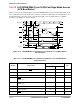
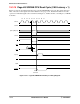
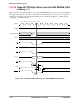
Figure 19-14. LCD Controller Timing Diagram (Self-Refresh Mode)
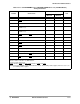
Table 19-15. LCD Controller Timing Parameters
Number Characteristic
(3.0 ± 0.3) V
Unit
Minimum Maximum
1 Line pulse to frame signal (4 * pixclk) - 2 —ns
2 Line pulse width (4 * pixclk) - 2 — ns
3 LCLK to data valid -2 2 ns
4 Shift clock to line pulse (2 * pixclk) - 2 (2 * pixclk) + 2 ns
Note:
The preceding data is measured by summing the polarity bits LFLM, LLP, and LCLK in the POLCF register.
The variable pixclk = LCD_CLK / (pcd + 1).
The self-refresh mode timing between LFRM, LSCLK, LD, and LLP are the same as in normal mode.
The self-refresh mode is entered and exited on the positive edge of LFRM.
In self-refresh mode, the LFRM and LLP waveforms are identical to the waveforms in normal mode, while LD and
LCLK remain in inactive level.
LFLM
LD[7:0]
LLP
LCLK
LREF
Self-Refresh Mode