
MC68VZ328 Integrated Processor User's Manual


16-8 MC68VZ328 User’s Manual
Programming Model
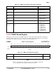
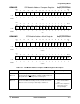
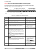
16.2.3 In-Circuit Emulation Module Control Register
The in-circuit emulation module control register (ICEMCR) is used to control the in-circuit emulation
module. The bit assignments for the ICE module control register are shown in the following register
display. The settings for the bits are described in Table 16-4.
ICEMCR ICE Module Control Register 0x(FF)FFFFFD0C
BIT 151413121110987654 3 2 1BIT 0
SWEN BBIEN HMDIS SB PBEN CEN
TYPE
rw rw rw rw rw rw
RESET
0 00000000000 0 0 0 0
0x0000
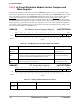
Table 16-4. ICE Module Control Register Description
Name Description Setting
Reserved
Bits 15–7
Reserved These bits are reserved and should
be set to 0.
SWEN
Bit 6
Software Enable EMU Module—In normal mode, writing to
this bit enables the breakpoint function.
0 = Disable breakpoint function.
1 = Enable breakpoint function.
Reserved
Bit 5
Reserved This bit is reserved and should be
set to 0.
BBIEN
Bit 4
Bus Break Interrupt Enable—When set, this bit enables the
generation of a level 7 interrupt on a bus breakpoint.
0 = Disable level 7 interrupt
generation on a bus breakpoint.
1 = Enable level 7 interrupt
generation on a bus breakpoint.
HMDIS
Bit 3
Hard-Map Disable—In emulation mode, this bit activates the
internal hard-map operation. When this bit is clear, some
memory locations are hard-coded to the specific values
shown in Table 16-5 on page 16-9. If this bit is set or in nor-
mal mode, memory reads to these locations refer to the exter-
nal memory.
Note: It is important to note that when writing to these
locations, all writes are occurring to external memory. When
the HMDIS bit is disabled, reads to these addresses are in
word or long-word sizes.
See Table 16-5 on page 16-9.
SB
Bit 2
Single BreakPoint—This bit controls the direction of the
EMUBRK
signal. In multiple breakpoint mode, the external
address comparator will compare the lower address bits and
the internal comparator will compare the higher address bits
to generate a breakpoint matched signal.
0 = Configure the EMUBRK
signal as
an input (multiple breakpoint
mode with external address
compare for the lower
addresses).
1 = Configure the EMUBRK
signal as
an output (single breakpoint
based on the internal address
compare register).
PBEN
Bit 1
Program Break Enable—This bit is used to select a program
or bus break.
0 = Select a bus break.
1 = Select a program break.