
MC68VZ328 Integrated Processor User's Manual

15-10 MC68VZ328 User’s Manual
PWM 2
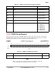
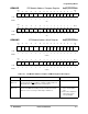
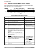
15.5.3 PWM 2 Pulse Width Register
This register controls the pulse width of PWM 2. The register bit assignments are shown in the following
register display. The register settings are described in Table 15-7.
PWMW2 PWM 2 Pulse Width Control Register 0x(FF)FFF514
NOTE:
If PWMW2 is greater than the period register PWMP2, the output will
never be reset. The resulting duty cycle is 100 percent.
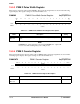
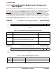
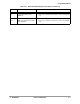
15.5.4 PWM 2 Counter Register
This register indicates the current counter value for PWM 2. The register bit assignments are shown in the
following register display. The register settings are described in Table 15-8.
PWMCNT2 PWM 2 Counter Register 0x(FF)FFF516
BIT
15
14 13 12 11 10 987654321
BIT
0
WIDTH
TYPE rw rw rw rw rw rw rw rw rw rw rw rw rw rw rw rw
RESET
0 0 0 0 0 0 0000000000
0x0000
Table 15-7. PWM 2 Pulse Width Control Register Description
Name Description Setting
WIDTH
Bits 15-0
Width—When the counter matches the value in this register, the output is
reset.
None
BIT 151413121110987654321BIT 0
COUNT
TYPE rw rw rw rw rw rw rw rw rw rw rw rw rw rw rw rw
RESET
0 00000000000000 0
0x0000
Table 15-8. PWM 2 Counter Register Description
Name Description Setting
COUNT
Bits 15–0
Count—Indicates the current counter value. None