
MC68VZ328 Integrated Processor User's Manual

15-8 MC68VZ328 User’s Manual
PWM 2
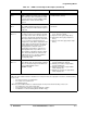
15.5 PWM 2
PWM 2 is a 16-bit PWM module that is compatible with the one used in the original DragonBall processor,
MC68328. Besides the difference in the PWM code size (8-bit versus 16-bit), the major difference between
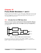
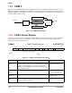
PWM 2 and PWM 1 is that PWM 2 does not have a data FIFO. Figure 15-4 illustrates the block diagram of
the pulse-width modulator unit 2.
Figure 15-4. PWM 2 Block Diagram
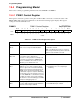
15.5.1 PWM 2 Control Register
This register controls how the overall pulse-width modulator operates. Output pin status is also maintained
in this register. The register bit assignments are shown in the following register display. The register
settings are described in Table 15-5.
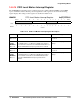
PWMC2 PWM 2 Control Register 0x(FF)FFF510
BIT 15 14 13 12 11 10 9 8 7 6 5 4 3 2 1
BIT
0
PWMIRQ IRQEN
LOAD PIN POL PWMEN CLKSEL
TYPE rw rw
rw rw rw rw rw rw rw
RESET
0000000000000000
0x0000
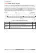
Table 15-5. PWM 2 Control Register Description
Name Description Setting
PWMIRQ
Bit 15
PWM Interrupt—This bit indicates that a period compare posted
an interrupt. This bit may also be set to immediately post a PWM
interrupt for debugging purposes. This bit is cleared after it is
read while set. If the IRQEN bit is 0, this bit can be polled for the
period comparator status.
0 = No PWM period rollover.
1 = PWM period rolled over.
IRQEN
Bit 14
Interrupt Enable—This bit enables the PWM interrupt. 0 = Disable PWM interrupt.
1 = Enable PWM interrupt.
Reserved
Bits 13–9
Reserved These bits are reserved and
should be set to 0.
LOAD
Bit 8
Load New Setting—This bit forces a new period value and width
data to the registers. It automatically clears itself after the loading
operation has been performed.
See description.
Width Compare
PWMO
Output
Control
Prescaler
Counter
SYSCLK
Period Compare