
MC68VZ328 Integrated Processor User's Manual

Programming Model
Pulse-Width Modulator 1 and 2 15-7
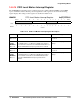
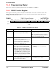
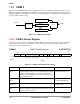
15.4.3 PWM 1 Period Register
This register controls the pulse-width modulator period. When the counter value matches PERIOD + 1, the
counter is reset to start another period. Therefore, the following equation applies:
PWMO (Hz) = PCLK (Hz) / (PERIOD + 2)
Eqn. 15-1
Writing 0xFF to this register achieves the same result as writing 0xFE.
The register bit assignments are shown in the following register display. The register settings are described
in Table 15-3.
PWMP1 PWM 1 Period Register 0x(FF)FFF504
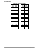
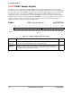
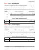
15.4.4 PWM 1 Counter Register
This register contains the current count value and can be read at any time without disturbing the counter.
The register bit assignments are shown in the following register display. The register settings are described
in Table 15-4.
PWMCNT1 PWM 1 Counter Register 0x(FF)FFF505
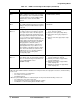
BIT 7 6 5 4 3 2 1 BIT 0
PERIOD
TYPE rw rw rw rw rw rw rw rw
RESET
1 111111 0
0xFE
Table 15-3. PWM 1 Period Register Description
Name Description Setting
PERIOD
Bits 7–0
Period—This field represents the pulse-width modulator’s period control value. None
BIT 7654321BIT 0
COUNT
TYPE rrrrrrrr
RESET
00000000
0x00
Table 15-4. PWM 1 Counter Register Description
Name Description Setting
COUNT
Bits 7–0
Count—This field represents the value of the current count. None