
MC68VZ328 Integrated Processor User's Manual

15-6 MC68VZ328 User’s Manual
Programming Model
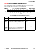
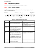
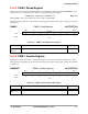
15.4.2 PWM 1 Sample Register
This register serves as the input to the FIFO. When successive audio sample values are written to this
register, they are automatically loaded into the FIFO in big-endian format. If 16-bit words are loaded, high
byte is first placed into the 8-bit FIFO, and then low byte. When individual sample bytes are being written,
they must be written to the low byte (SAMPLE1) only. The pulse-width modulator will revert to free
running at the duty-cycle setting that was set last until the FIFO is reloaded or the pulse-width modulator is
disabled. If the value in this register is higher than the PERIOD + 1, the output will never be reset, which
results in a 100-percent duty cycle. The register bit assignments are shown in the following register
display. The register settings are described in Table 15-2.
PWMS1 PWM 1 Sample Register 0x(FF)FFF502
BIT
15
14 13 12 11 10 987654321
BIT
0
SAMPLE0 SAMPLE1
TYPE rw rw rw rw rw rw rw rw rw rw rw rw rw rw rw rw
RESET
XXXXXXXXXXXXXXXX
0xXXXX
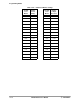
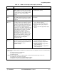
Table 15-2. PWM 1 Sample Register Description
Name Description Setting
SAMPLE0
Bits 15–8
Sample 0—This field represents the high byte of a two-sample word. This byte is pre-
sented to the pulse-width modulator before the SAMPLE1 field.
None
SAMPLE1
Bits 7–0
Sample 1—This field represents the low byte of a two-sample word. This byte will be
presented to the pulse-width modulator after the SAMPLE0 field. When used with single
8-bit samples, data must be written to this byte.
None