
MC68VZ328 Integrated Processor User's Manual


Programming Model
Universal Asynchronous Receiver/Transmitter 1 and 2 14-25
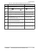
FIFO
HALF
Bit 14
FIFO Half (FIFO Status)—This read-only bit indicates that the
transmitter FIFO is less than half full. This bit generates a
maskable interrupt.
0 = Transmitter FIFO is more than
half full
1 = Transmitter FIFO is less than
half full
TX
AVAIL
Bit 13
Transmit FIFO Has a Slot Available (FIFO Status)—This
read-only bit indicates that the transmitter FIFO has at least
one slot available for data. This bit generates a maskable
interrupt.
0 = Transmitter does not need data
1 = Transmitter needs data
SEND
BREAK
Bit 12
Send Break (Tx Control)—This bit forces the transmitter to
immediately send continuous zeros, which creates a break
character. See Section 14.3.1.2, “CTS Signal Operation,” for a
description of how to generate a break.
0 = Normal transmission
1 = Send break (continuous zeros)
NOCTS2
Bit 11
Ignore CTS2 (Tx Control)—When this bit is high, it forces the
CTS
2 signal that is presented to the transmitter to always be
asserted, which effectively ignores the external pin.
0 = Transmit only while the CTS2
signal is asserted
1 = Ignore the CTS2 signal
BUSY
Bit 10
Busy (Tx Status)—When this bit is high, it indicates that the
transmitter is busy sending a character. This bit is asserted
while the transmitter state machine is not idle or the FIFO has
data in it.
0 = Transmitter is not sending a
character
1 = Transmitter is sending a
character
CTS2
STAT
Bit 9
CTS2
Status (CTS2 Bit)—This bit indicates the current status
of the CTS
2 signal. A “snapshot” of the pin is taken immedi-
ately before this bit is presented to the data bus. While the
NOCTS2 bit is high, this bit can serve as a general-purpose
input.
0 = CTS2
signal is low
1 = CTS2
signal is high
CTS2
DELTA
Bit 8
CTS2 Delta (CTS2 Bit)—When this bit is high, it indicates that
the CTS
2 signal changed state and generates a maskable
interrupt. The current state of the CTS
2 signal is available on
the CTS2 STAT bit. An immediate interrupt may be generated
by setting this bit high. The CTS2 interrupt is cleared by writing
0 to this bit.
0 = CTS2 signal did not change
state since it was last cleared
1 = CTS2 signal has changed state
TX
DATA
Bits 7–0
Tx Data (Character) (Write-Only)—This write-only field is the
parallel transmit-data input. In 7-bit mode, bit 7 is ignored, and
in 8-bit mode, all of the bits are used. Data is transmitted with
the least significant bit first. A new character is transmitted
when this field is written and has passed through the FIFO.
See description
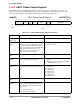
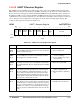
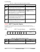
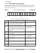
Table 14-13. UART 2 Transmitter Register Description (Continued)
Name Description Setting