
MC68VZ328 Integrated Processor User's Manual

14-12 MC68VZ328 User’s Manual
Programming Model
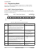
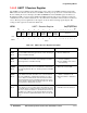
14.4.2 UART 1 Baud Control Register
The UART 1 baud control (UBAUD1) register controls the operation of the baud rate generator, the
integer prescaler, and the UCLK signal. The bit position assignments for this register are shown in the
following register display. The settings for this register are described in Table 14-5.
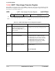
UBAUD1 UART 1 Baud Control Register 0x(FF)FFF902
BIT 15 14 13 12 11 10 9 8 7 6 5 4 3 2 1 BIT 0
UCL
KDI
R
BAU
D
SRC
DIVIDE
PRESCALER
TYPE
rw rw rw rw rw rw rw rw rw rw rw
RESET
0 0 0 0 0 0000011111 1
0x003F
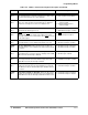
Table 14-5. UART 1 Baud Control Register Description
Name Description Setting
Reserved
Bits 15–14
Reserved These bits are reserved and should be set to
0.
UCLKDIR
Bit 13
UCLK Direction—This bit controls the direction
of the UCLK signal. When this bit is low, the sig-
nal is an input, and when it is high, it is an output.
However, the SELx bit in the Port E registers
must be 0. See Section 10.4.6, “Port E Regis-
ters,” on page 10-21 for more information.
0 = UCLK is an input.
1 = UCLK is an output.
Reserved
Bit 12
Reserved This bit is reserved and should be set to 0.
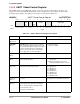
BAUD SRC
Bit 11
Baud Source—This bit controls the clock source
to the baud rate generator.
0 = Baud rate generator source is from
system clock.
1 = Baud rate generator source is from
UCLK pin (UCLKDIR must be set to 0).
DIVIDE
Bits 10–8
Divide—These bits control the clock frequency
produced by the baud rate generator.
000 = Divide by 1.
001 = Divide by 2.
010 = Divide by 4.
011 = Divide by 8.
100 = Divide by 16.
101 = Divide by 32.
110 = Divide by 64.
111 = Divide by 128.
Reserved
Bits 7–6
Reserved These bits are reserved and should be set to
0.
PRESCALER
Bits 5–0
Prescaler—These bits control the division value
of the baud generator prescaler. The division
value is determined by the following formula:
Prescaler division value =
65 (decimal) – PRESCALER
See description.