
MC68VZ328 Integrated Processor User's Manual


12-12 MC68VZ328 User’s Manual
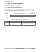
Programming Model
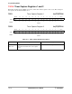
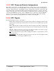
12.2.6 Timer Status Registers 1 and 2
Each timer status (TSTATx) register indicates the corresponding timer’s status. When a capture event
occurs, it is indicated by setting the CAPT bit. When a compare event occurs, the COMP bit is set. Both
bits are cleared by writing 0x0. To be cleared, these bits must first be examined, and the bit must have a
value of 0x1. This ensures that an interrupt will not be missed if it occurs between the status read and when
the interrupt is cleared. The settings for the registers are described in Table 12-7.
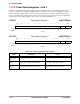
TSTAT1 Timer Status Register 1 0x(FF)FFF60A
TSTAT2 Timer Status Register 2 0x(FF)FFF61A
BIT
15
14 13 12 11 10 98765432 1 BIT 0
Not Used CAPT COMP
TYPE rw rw rw rw rw rw rw rw rw rw rw rw rw rw rw rw
RESET
0 0 0 0 0 0 00000000 0 0
0x0000
BIT
15
14 13 12 11 10 98765432 1 BIT 0
Not Used CAPT COMP
TYPE rw rw rw rw rw rw rw rw rw rw rw rw rw rw rw rw
RESET
0 0 0 0 0 0 00000000 0 0
0x0000
Table 12-7. Timer Status Register Description
Name Description Setting
Not used
Bits 15–2
These bits are not used. —
CAPT
Bit 1
Capture Event—This status bit, when set,
indicates that a capture event occurred.
0 = No capture event occurred.
1 = A capture event has occurred.
COMP
Bit 0
Compare Event—This status bit, when set,
indicates when a compare event occurs.
0 = No compare event occurred.
1 = A compare event has occurred.