
MC68VZ328 Integrated Processor User's Manual


12-10 MC68VZ328 User’s Manual
Programming Model
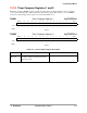
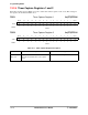
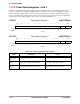
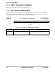
12.2.4 Timer Capture Registers 1 and 2
Each timer capture register (TCRx) stores the counter value when a capture event occurs. The settings for
the registers are described in Table 12-5.
TCR1 Timer Capture Register 1 0x(FF)FFF606
TCR2 Timer Capture Register 2 0x(FF)FFF616
BIT 15 14 13 12 11 10 9 8 7 6 5 4 3 2 1 BIT 0
CAPTURE
TYPE rw rw rw rw rw rw rw rw rw rw rw rw rw rw rw rw
RESET
0 00000000000000 0
0x0000
BIT 15 14 13 12 11 10 9 8 7 6 5 4 3 2 1 BIT 0
CAPTURE
TYPE rw rw rw rw rw rw rw rw rw rw rw rw rw rw rw rw
RESET
0 00000000000000 0
0x0000
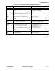
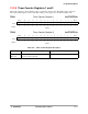
Table 12-5. Timer Capture Register Description
Name Description Setting
CAPTURE
Bits 15–0
Capture Value—This field stores the counter
value that existed at the time of the capture
event.
This field has a valid range 0x0000 to 0xFFFF.