
MC68VZ328 Integrated Processor User's Manual

12-6 MC68VZ328 User’s Manual
Programming Model
12.2 Programming Model
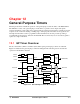
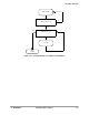
The following sections provide programming information about the settings of the two 16-bit timers in the
GP timers module. Because the two timers are identical, the register description and the associated table
describing the register settings apply to both registers.
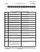
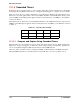
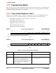
12.2.1 Timer Control Registers 1 and 2
Each timer control (TCTLx) register controls the overall operation of its corresponding GP timer. The
settings for the registers are described in Table 12-2. The TCTL registers control the following:
• Selecting the free-running or restart mode after a compare event
• Selecting the capture trigger event
• Controlling the output compare mode
• Enabling the compare event interrupt
• Selecting the prescaler clock source
• Enabling and disabling the GP Timer
TCTL1 Timer Control Register 1 0x(FF)FFF600
TCTL2 Timer Control Register 2 0x(FF)FFF610
BIT
15
14 13 12 11 10 9 8 7 6 5 4 3 2 1
BIT
0
FRR CAP OM IRQEN CLKSOURCE TEN
TYPE
rw rw rw rw rw rw rw rw rw
RESET
00000000000 0 0000
0x0000
BIT
15
14 13 12 11 10 9 8 7 6 5 4 3 2 1
BIT
0
FRR CAP OM IRQEN CLKSOURCE TEN
TYPE
rw rw rw rw rw rw rw rw rw
RESET
00000000000 0 0000
0x0000
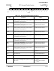
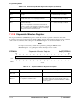
Table 12-2. Timer Control Register Description
Name Description Setting
Reserved
Bits 15–9
Reserved These bits are reserved and should be set to 0.
FRR
Bit 8
Free-Running/Restart—This bit controls the
counter mode of operation after a compare
event occurs. In free-running mode, the
counter continues after the compare. In restart
mode, the counter resets to 0x0000 and
resumes counting.
0 = Restart mode (default).
1 = Free-running mode.