
MC68VZ328 Integrated Processor User's Manual

Programming Model
Real-Time Clock 11-11
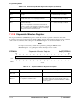
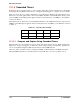
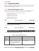
RTCISR RTC Interrupt Status Register 0x(ff)FFFB0E
BIT
15
14 13 12 11 10 9 8 7 6 5 4 3 2 1
BIT
0
RIS7 RIS6 RIS5 RIS4 RIS3 RIS2 RIS1 RIS0 HR 1HZ DAY ALM MIN SW
TYPE rw rw rw rw rw rw rw rw rw rw rw rw rw rw
RESET
0 0 0 0 0 0 0 0 0 0 0 0 0 0 0 0
0x0000
Table 11-8. RTC Interrupt Status Register Description
Name Description Setting
RIS7
Bit 15
Real-Time Interrupt Status Bit 7—This bit
shows the status of real-time interrupt 7.
0 = No RIS7 interrupt occurred.
1 = RIS7 interrupt occurred.
RIS6
Bit 14
Real-Time Interrupt Status Bit 6—This bit
shows the status of real-time interrupt 6.
0 = No RIS6 interrupt occurred.
1 = RIS6 interrupt occurred.
RIS5
Bit 13
Real-Time Interrupt Status Bit 5—This bit
shows the status of real-time interrupt 5.
0 = No RIS5 interrupt occurred.
1 = RIS5 interrupt occurred.
RIS4
Bit 12
Real-Time Interrupt Status Bit 4—This bit
shows the status of real-time interrupt 4.
0 = No RIS4 interrupt occurred.
1 = RIS4 interrupt occurred.
RIS3
Bit 11
Real-Time Interrupt Status Bit 3—This bit
shows the status of real-time interrupt 3.
0 = No RIS3 interrupt occurred.
1 = RIS3 interrupt occurred.
RIS2
Bit 10
Real-Time Interrupt Status Bit 2—This bit
shows the status of real-time interrupt 2.
0 = No RIS2 interrupt occurred.
1 = RIS2 interrupt occurred.
RIS1
Bit 9
Real-Time Interrupt Status Bit 1—This bit
shows the status of real-time interrupt 1.
0 = No RIS1 interrupt occurred.
1 = RIS1 interrupt occurred.
RIS0
Bit 8
Real-Time Interrupt Status Bit 0—This bit
shows the status of real-time interrupt 0.
0 = No RIS0 interrupt occurred.
1 = RIS0 interrupt occurred.
Reserved
Bits 7–6
Reserved These bits are reserved and should be set to 0.
HR
Bit 5
Hour Flag—This bit is set on every increment
of the hour counter in the TOD clock.
0 = No 1-hour interrupt occurred.
1 = A 1-hour interrupt occurred.
1HZ
Bit 4
1 Hz Flag—If enabled, this bit is set on every
increment of the second counter in the TOD
clock.
0 = No 1 Hz interrupt occurred.
1 = A 1 Hz interrupt occurred.
DAY
Bit 3
Day Flag—If enabled, this bit is set for every
24-hour clock increment (at midnight)
of the
day counter in the TOD clock, and an interrupt
is posted .
0 = No 24-hour rollover interrupt occurred.
1 = A 24-hour rollover interrupt occurred.
ALM
Bit 2
Alarm Flag—If this bit is enabled, an alarm
flag is set on a compare match between the
real-time clock and the alarm register’s value.
Note: The alarm will recur every 24 hours.
For a single alarm, clear the interrupt enable in
the interrupt service routine.
0 = No alarm interrupt occurred.
1 = An alarm interrupt occurred.