
MC68VZ328 Integrated Processor User's Manual

Programming Model
Real-Time Clock 11-9
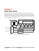
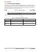
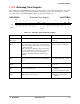
11.2.5 Watchdog Timer Register
The watchdog timer (WATCHDOG) register provides all of the control of the watchdog timer. It provides
bits to enable the watchdog timer and to determine if the result of a time out is an interrupt or a system
reset. The settings for the WATCHDOG register are described in Table 11-6.
WATCHDOG Watchdog Timer Register 0x(ff)FFFB0A
BIT
15
14 13 12 11 10 9 8 7 6 5 4 3 2 1
BIT
0
CNTR INTF ISEL EN
TYPE rw rw rw rw rw
RESET
0 0 0 0 0 0 0 0 0 0 0 0 0 0 0 1
0x0001
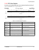
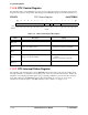
Table 11-6. Watchdog Timer Register Description
Name Description Setting
Reserved
Bits 15–10
Reserved These bits are reserved and should
be set to 0.
CNTR
Bits 9–8
Counter—These bits represent the value of the watch-
dog counter, which counts up in 1-second increments.
When the watchdog counter counts to 10, it generates
a watchdog interrupt.
Note: Because the watchdog counter is incremented
by a 1 Hz signal from the real-time clock, the average
tolerance of the counter is 0.5 seconds. Greater
accuracy is obtained by polling the 1 Hz flag of the
RTCISR.
Writing any value to these bits will
reset the counter to 00 (default).
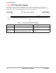
INTF
Bit 7
Interrupt Flag—When this bit is set, a watchdog inter-
rupt has occurred. This bit can be cleared by writing a
1 to it.
0 = No watchdog interrupt occurred.
1 = A watchdog interrupt occurred.
Reserved
Bits 6–2
Reserved These bits are reserved and should
be set to 0.
ISEL
Bit 1
Interrupt Selection—This bit selects the watchdog
reset. It is cleared at reset.
0 = Selects the watchdog reset
(default).
1 = Select the watchdog interrupt.
EN
Bit 0
Watchdog Timer Enable—This bit enables the
watchdog timer. It is set at reset.
0 = Disable the watchdog timer.
1 = Enable the watchdog timer
(default).