
MC68VZ328 Integrated Processor User's Manual

Programming Model
I/O Ports 10-19
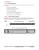
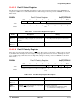
10.4.5.5 Port D Select Register
The Port D select register (PDSEL) determines if a bit position in the Port D data register (PDDATA) is
assigned as a GPIO or to a dedicated I/O function. The settings for the bit positions of PDSEL are shown in
Table 10-21.
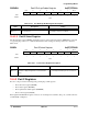
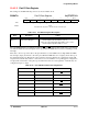
PDSEL Port D Select Register 0x(FF)FFF41B
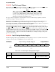
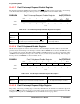
10.4.5.6 Port D Polarity Register
These bits select the input signal polarity of INT[3:0]. The polarity of the rising or falling edge is selected
by the POLx bits. Interrupts are active high (or rising edge) when these bits are low. Interrupts are active
low (or falling edge) while these bits are high. The settings for the bit positions of PDPOL are shown in
Table 10-22.
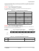
PDPOL Port D Polarity Register 0x(FF)FFF41C
BIT 7654321BIT 0
SEL7 SEL6 SEL5 SEL4
TYPE rw rw rw rw
RESET
11110000
0xF0
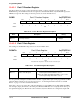
Table 10-21. Port D Select Register Description
Name Description Setting
SELx
Bits 7–4
Select—These bits select whether the internal
chip function or I/O port signals are connected to
the pins.
0 = The dedicated function pins are connected.
1 = The I/O port function pins are connected.
Reserved
Bits 3–0
Reserved These bits are reserved and should be set to 0.
BIT 7654321BIT 0
POL3 POL2 POL1 POL0
TYPE
rw rw rw rw
RESET
00000000
0x00
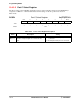
Table 10-22. Port D Polarity Register Description
Name Description Setting
Reserved
Bits 7–4
Reserved These bits are reserved and should be set to 0.
POLx
Bits 3–0
Polarity—These bits determine the input signal
polarity of INT
[3:0] interrupts.
0 = Data is unchanged.
1 = The input data is inverted before being
presented to the holding register.