
MC68VZ328 Integrated Processor User's Manual

Programming Model
I/O Ports 10-13
accept the data, but the data written to each cannot be accessed until the corresponding pin is configured as
an output. The actual value on the pin is reported when these bits are read, regardless of whether they are
configured as input or output.
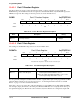
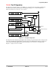
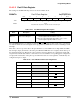
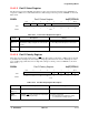
10.4.3.3 Port C Dedicated I/O Functions
The eight PCDATA lines are multiplexed with the LCD controller dedicated I/O signals whose
assignments are shown in Table 10-14.
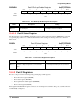
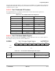
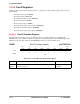
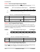
10.4.3.4 Port C Pull-down Enable Register
The Port C pull-down enable register (PCPDEN) controls the pull-down resistors for each line in Port C.
The settings for the bit positions are shown in Table 10-15.
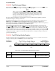
PCPDEN Port C Pull-down Enable Register 0x(FF)FFF412
Table 10-14. Port C Dedicated Function Assignments
Bit GPIO Function Dedicated I/O Function
0 Data bit 0 LD0
1 Data bit 1 LD1
2 Data bit 2 LD2
3 Data bit 3 LD3
4 Data bit 4 LFLM
5 Data bit 5 LLP
6 Data bit 6 LCLK
7 Data bit 7 LACD
BIT 7654321BIT 0
PD7PD6PD5PD4PD3PD2PD1PD0
TYPE rw rw rw rw rw rw rw rw
RESET
11111111
0xFF
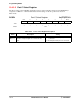
Table 10-15. Port C Pull-down Enable Register Description
Name Description Setting
PDx
Bits 7–0
Pull-down—These bits enable the pull-down resistors on the
port.
0 = Pull-down resistors are disabled
1 = Pull-down resistors are enabled