
MC68VZ328 Integrated Processor User's Manual


Programming Model
I/O Ports 10-7
10.4.1.1 Port A Direction Register
The Port A direction register controls the direction (input or output) of the line associated with the
PADATA bit position. The settings for the bit positions are shown in Table 10-4.
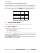
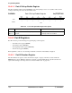
PADIR Port A Direction Register 0x(FF)FFF400
10.4.1.2 Port A Data Register
The eight PADATA bits control or report the data on the pins while the associated SELx bits are high.
While the DIRx bits are high (output), the Dx bits control the pins. While the DIRx bits are low (input), the
Dx bits report the signal driving the pins. The Dx bits can be written at any time. Bits that are configured as
inputs will accept the data, but the data written to each cannot be accessed until the respective pin is
configured as an output. The actual value on the pin is reported when these bits are read, regardless of
whether they are configured as input or output. The settings for the bit positions are shown in Table 10-5.
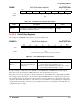
PADATA Port A Data Register 0x(FF)FFF401
BIT 7654321BIT 0
DIR7 DIR6 DIR5 DIR4 DIR3 DIR2 DIR1 DIR0
TYPE rw rw rw rw rw rw rw rw
RESET
00000000
0x00
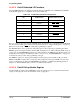
Table 10-4. Port A Direction Register Description
Name Description Setting
DIRx
Bits 7–0
Direction—These bits control the direction of the pins in an 8-bit
system.
0 = Input
1 = Output
BIT 7654321BIT 0
D7 D6 D5 D4 D3 D2 D1 D0
TYPE rw rw rw rw rw rw rw rw
RESET
11111111
0xFF*
*Actual bit value depends on external circuits connected to pin.
Table 10-5. Port A Data Register Description
Name Description Setting
Dx
Bits 7–0
Data—These bits reflect the
status of the I/O signal in an
8-bit system.
0 = Drives the output signal low when DIRx is set to 1 or the
external signal is low when DIRx is set to 0
1 = Drives the output signal high when DIRx is set to 1 or the
external signal is high when DIRx is set to 0