
MC68VZ328 Integrated Processor User's Manual


10-4 MC68VZ328 User’s Manual
I/O Port Operation
10.2.3 Summary of Port Behavior During Reset
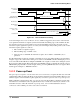
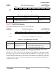
Table 10-2 summarizes the behavior of all MC68VZ328 I/O ports during the Reset Assertion Time Length
(see Figure 10-1 on page 10-3) for power-up resets and warm resets.
10.3 I/O Port Operation
The following subsections describe details of the I/O ports’ operation.
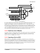
10.3.1 Data Flow from the I/O Module
The operation of a port connected to another module in the MC68VZ328 is illustrated in Figure 10-2 on
page 10-5.
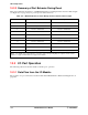
Table 10-2. MC68VZ328 I/O Port Status During the Reset Assertion Time Length
I/O Ports Warm Reset Power-up Reset
A Resets to default state Resets to default state
B Maintains previous state Unknown state
C Resets to default state Resets to default state
D Resets to default state Resets to default state
E Resets to default state Resets to default state
F Resets to default state Resets to default state
G Resets to default state Resets to default state
J Resets to default state Resets to default state
K Resets to default state Resets to default state
M Maintains previous state Unknown state
Note: The default state is defined by the reset values of the corresponding I/O port’s registers. Please refer to
Table 3-1 on page 3-2 and Table 3-2 on page 3-8 for details.