
MC68VZ328 Integrated Processor User's Manual

9-12 MC68VZ328 User’s Manual
Programming Model
9.6.4 Interrupt Status Register
During the interrupt service, the interrupt handler determines the source of interrupts by examining the
interrupt status register (ISR). When the bits in this register are set, they indicate that the corresponding
interrupt is posted to the core. If there are multiple interrupt sources at the same level, the software handler
may need to prioritize them, depending on the application.
Each interrupt status bit in this register reflects the interrupt request from its respective interrupt source.
When programmed as edge-triggered interrupts, external interrupts I
NT[3:0], IRQ1, IRQ2, IRQ3, and
IRQ6
can be cleared by writing a 1 to the corresponding status bit in the register. When programmed as
level-triggered interrupts, these interrupts are cleared at the requesting sources. All interrupts from internal
peripheral devices are level-triggered interrupts to the interrupt handler, and they are cleared at the
requesting sources.
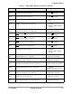
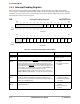
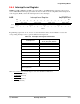
ISR Interrupt Status Register 0xFFFFF30C
BIT
31
30 29 28 27 26 25 24 23 22 21 20 19 18 17
BIT
16
EMI
Q
RTI
SPI
1
IRQ
5
1R
Q6
IRQ
3
IRQ
2
IRQ
1
TYPE
rw rw rw rw rw rw rw rw
RESET0000000000000000
0x00000000
BIT
15
1413121110987654321
BIT
0
PW
M2
UA
RT
2
INT
3
INT
2
INT
1
INT
0
PW
M1
KB
TM
R2
RT
C
WD
T
UA
RT
1
TM
R1
SPI
2
TYPE
rw rw rw rw rw rw rw rw rw rw rw rw rw rw
RESET
0000000000000000
0x00000000
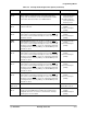
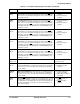
Table 9-6. Interrupt Status Register Description
Name Description Settings
Reserved
Bits 31–24
Reserved These bits are reserved
and should be set to 0.
EMIQ
Bit 23
Emulator Interrupt Status—When set, this bit indicates that the
in-circuit emulation module or EMUIRQ
pin is requesting an interrupt
on level 7. This bit can be generated from three interrupt sources:
two breakpoint interrupts from the in-circuit emulation module and an
external interrupt from EMUIRQ
, which is an active low, edge-sensi-
tive interrupt. To clear this interrupt, you must read the ICEMSR reg-
ister to identify the interrupt source and write a 1 to the
corresponding bit of that register. See Section 16.2.4, “In-Circuit
Emulation Module Status Register,” on page 16-10 for more infor-
mation.
0 = No emulator interrupt is
pending.
1 = An emulator interrupt is
pending.