
MC68VZ328 Integrated Processor User's Manual


9-8 MC68VZ328 User’s Manual
Programming Model
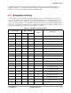
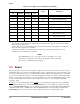
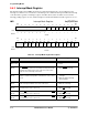
9.6.2 Interrupt Control Register
The interrupt control register (ICR) controls the behavior of the external interrupt inputs. It informs the
interrupt controller whether the interrupt signal is an edge-triggered or a level-sensitive interrupt, as well as
whether it has positive or negative polarity. The bit assignments for this register are shown in the following
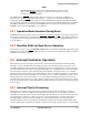
register display, and the settings for the bit positions are listed in Table 9-4.
ICR Interrupt Control Register 0x(FF)FFF302
BIT 15 14 13 12 11 10 9 8 7 6 5 4 3 2 1 BIT 0
POL1 POL2 POL3 POL6 ET1 ET2 ET3 ET6 POL5
TYPE rw rw rw rw rw rw rw rw rw
RESET
0 0 0 0 0 0 0 0 0 000000 0
0x0000
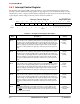
Table 9-4. Interrupt Control Register Description
Name Description Setting
POL1
Bit 15
Polarity Control 1—This bit controls interrupt polarity for the IRQ1
signal. In
level-sensitive mode, negative polarity produces an interrupt when the signal is
at logic level low. Positive polarity produces an interrupt when the signal is at
logic level high. In edge-triggered mode, negative polarity produces an interrupt
when the signal goes from logic level high to logic level low. Positive polarity
generates an interrupt when the signal goes from logic level low to logic level
high.
0 = Negative
polarity.
1 = Positive
polarity.
POL2
Bit 14
Polarity Control 2—This bit controls interrupt polarity for the IRQ2
signal. In
level-sensitive mode, negative polarity produces an interrupt when the signal is
at logic level low. Positive polarity produces an interrupt when the signal is at
logic level high. In edge-triggered mode, negative polarity produces an interrupt
when the signal goes from logic level high to logic level low. Positive polarity
generates an interrupt when the signal goes from logic level low to logic level
high.
0 = Negative
polarity.
1 = Positive
polarity.
POL3
Bit 13
Polarity Control 3—This bit controls interrupt polarity for the IRQ3
signal. In
level-sensitive mode, negative polarity produces an interrupt when the signal is
at logic level low. Positive polarity produces an interrupt when the signal is at
logic level high. In edge-triggered mode, negative polarity produces an interrupt
when the signal goes from logic level high to logic level low. Positive polarity
generates an interrupt when the signal goes from logic level low to logic level
high.
0 = Negative
polarity.
1 = Positive
polarity.
POL6
Bit 12
Polarity Control 6—This bit controls interrupt polarity for the IRQ6
signal. In
level-sensitive mode, negative polarity produces an interrupt when the signal is
at logic level low. Positive polarity produces an interrupt when the signal is at
logic level high. In edge-triggered mode, negative polarity produces an interrupt
when the signal goes from logic level high to logic level low. Positive polarity
generates an interrupt when the signal goes from logic level low to logic level
high.
0 = Negative
polarity.
1 = Positive
polarity.
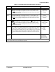
ET1
Bit 11
IRQ1
Edge Trigger Select—When this bit is set, the IRQ1 signal is an
edge-triggered interrupt. In edge-triggered mode, a 1 must be written to the
IRQ1 bit in the interrupt status register to clear this interrupt. When this bit is
low, IRQ1
is a level-sensitive interrupt. In this case, the external source of the
interrupt must be cleared.
0 = Level-sensitive
interrupt.
1 = Edge-sensitive
interrupt.