
MC68VZ328 Integrated Processor User's Manual


8-20 MC68VZ328 User’s Manual
Programming Model
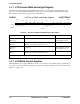
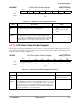
8.3.17 LCD Gray Palette Mapping Register
For four-level grayscale displays, full black and full white are the two predefined display levels. The other
two intermediate grayscale shading densities can be adjusted in the LCD gray palette mapping register
(LGPMR). The bit assignments for the register are shown in the following register display. The settings for
the bits in the register are listed in Table 8-17.
LGPMR LCD Gray Palette Mapping Register 0x(FF)FFFA33
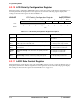
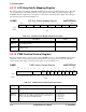
8.3.18 PWM Contrast Control Register
The pulse-width modulator contrast control register (PWMR) is used to control the PWMO signal, which
adjusts the contrast of the LCD panel. The bit assignments for the register are shown in the following
register display. The settings for the bits in the register are listed in Table 8-18.
PWMR PWM Contrast Control Register 0x(FF)FFFA36
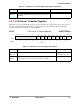
BIT 7654321BIT 0
G23 G22 G21 G20 G13 G12 G11 G10
TYPE rw rw rw rw rw rw rw rw
RESET
10000100
0x84
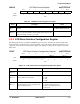
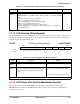
Table 8-17. LCD Gray Palette Mapping Register Description
Name Description Setting
G23–G20
Bits 7–4
Grayscale 23–20—These bits represent one of the two gray-
scale shading densities.
See description
G13–G10
Bits 3–0
Grayscale 13–10—These bits represent the other grayscale
shading density.
See description
BIT
15
14 13 12 11 10 9 8 7 6 5 4 3 2 1
BIT
0
SRC1–0
CCPE
N
PW
7
PW
6
PW
5
PW
4
PW
3
PW
2
PW
1
PW
0
TYPE
rw rw rw rw rw rw rw rw rw rw rw
RESET
000000 0 0 00000000
0x0000
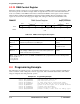
Table 8-18. PWM Contrast Control Register Description
Name Description Setting
Reserved
Bits 15–11
Reserved These bits are reserved and should
be set to 0.
SRC1–0
Bits 10–9
Source 1–0—These bits select the input clock source for the
PWM counter. The PWM output frequency is equal to the fre-
quency of the input clock divided by 256.
00 = Line pulse.
01 = Pixel clock.
10 = LCD clock.
11 = Reserved.